Section 4 - Troubleshooting Technical Support
505115-000 Pa
e 4-3
0-1 T
ECHNICAL
S
UPPORT
Technical Support is available by telephone of FAX.
U
P
R
IGHT
USA
Tel: 1-559-891-5200
FAX: 1-559-896-9244
U
P
R
IGHT
E
UROPE
Tel: +31-10-238-0000
FAX: +31-10-238-0001
0-2 G
ENERAL
P
ROCEDURE
Thoroughly study hydraulic and electronic schematics in the Schematics section. Check for loose con-
nections and short circuits. Check/repair/replace each component in the Truth Table which is listed under
each machine function which does not operate properly.
Determine whether the problem is mechanical (interference), electrical or hydraulic. Some functions
require power at more than one solenoid.
Use the charts on the following pages to help determine the cause of a fault in your UpRight work platform
NOTE: Spike protection diodes at components have been left out of the charts to eliminate confusion.
0-3 T
ROUBLESHOOTING
P
ROCEDURES
1.
Verify your problem
. Do a full function test from both platform controls and chassis controls and note all
functions that are not operating correctly.
2.
Narrow the possible causes of the malfunction
. Use the troubleshooting guide to determine which com-
ponents are common to all circuits that are not functioning correctly. To aid in troubleshooting, the letters
following the component on the table are the same as the component’s designation on the schematics.
3.
Identify the problem component
. Test components that are common to all circuits that are not functioning
correctly. Remember to check wires and terminals between suspect components. Be sure to check con-
nections to battery negative.
4.
Repair or replace component found to be faulty
.
5.
Verify that repair is complete
. Do a full function test from both the platform and chassis controls to verify
that all functions are operating correctly and that the machine is performing according to specifications.
A
DJUSTMENT
P
ROCEDURES
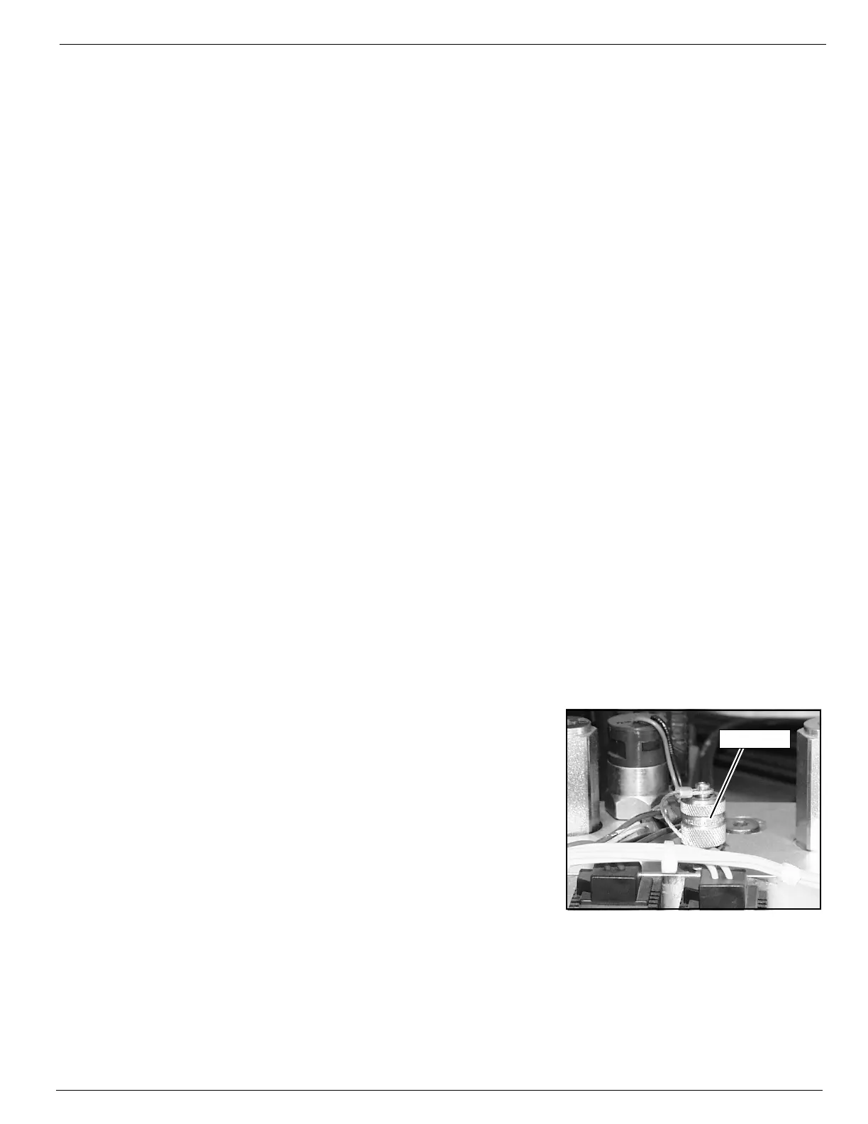
Figure 4-1: Hydraulic Test Port
Hydraulic settings must be checked whenever a component is
repaired or replaced.
Remove counterbalance valves and "bench test" them if they
are suspect.
Connect a pressure gauge of appropriate range to the test port
located on the hydraulic manifold.
NOTE: Correct pressure settings are listed in the hydraulic schematic.
C
HECKING
P
UMP
P
RESSURES
Remove hose from pump port and connect pressure tester.
Test Port

 Loading...


