Installation, Operating & Maintenance Instructions
Series 650 DN 100-250 (I.D. 4“ - 10”), CC-Link
VAT Vakuumventile AG, CH-9469 Haag, Switzerland
Tel +41 81 771 61 61 Fax +41 81 771 48 30 CH@vatvalve.com www.vatvalve.com
280672EB
2010-12-15
11/94
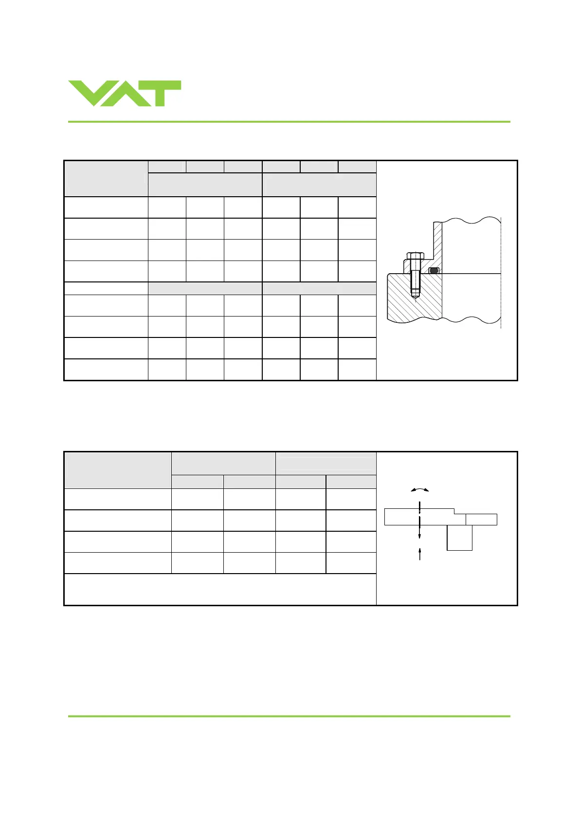
2.3.2 Mounting with O-ring in grooves
ISO-F JIS ASA-LP
ISO-F JIS ASA-LP
Valve size
max. tightening torque
(Nm)
max. tightening torque
(lbs . ft)
DN100 / 4“
(65040 - . . . . - . . . . )
20-23 35-40 35-40 15-17 26-30 26-30
DN160 / 6“
(65044 - . . . . - . . . . )
35-40 35-40 35-40 26-30 26-30 26-30
DN200 / 8“
(65046 - . . . . - . . . . )
35-40 35-40 80-90 26-30 26-30 59-67
DN250 / 10“
(65048 - . . . . - . . . . )
35-41 65-70 80-90 26-30 48-52 59-67
hole depth (mm) hole depth (inch)
DN100 / 4“
(65040 - . . . . - . . . . )
12 12 12 0.47 0.47 0.47
DN160 / 6“
(65044 - . . . . - . . . . )
14 14 14 0.55 0.55 0.55
DN200 / 8“
(65046 - . . . . - . . . . )
15 15 14 0.59 0.59 0.59
DN250 / 10“
(65048 - . . . . - . . . . )
16 16 16 0.63 0.63 0.63
2.4 Admissible forces
Forces from evacuating the system, from the weight of other components, and from baking can lead to deformation and
malfunctioning of the valve. Stress has to be relieved by suitable means, e.g. bellows sections.
Axial tensile or
compressive force «F
A
»
Bending moment «M»
Valve size
N lb. Nm lbf.
DN100 / 4“
(65040 - . . . . - . . . . )
1000 220 40 30
DN160 / 6“
(65044 - . . . . - . . . . )
2000 440 80 60
DN200 / 8“
(65046 - . . . . - . . . . )
2000 440 80 60
DN250 / 10“
(65048 - . . . . - . . . . )
2500 550 100 75
For a combination of both forces (F
A
and M) the values are invalid.
Verify that the depth of the mounting screws is min. 1 x thread diameter.
Please contact VAT for more information.
F
A
M

 Loading...


