Installation, Operating & Maintenance Instructions
Series 650 DN 100-250 (I.D. 4“ - 10”), CC-Link
VAT Vakuumventile AG, CH-9469 Haag, Switzerland
Tel +41 81 771 61 61 Fax +41 81 771 48 30 CH@vatvalve.com www.vatvalve.com
280672EB
2010-12-15
33/94
3.1.7 Safety mode
By means of an external switch (see connection diagrams «Electrical connection») the motor power supply can be
interrupted. In this case the valve enters the ‘safety mode’. This motor interlock prevents the valve from moving (e.g.
maintenance work). Data reading from the control unit remains possible.
When motor interlock is active during power up the valve directly enters the ‘safety mode’ and is not able to synchronize.
Display shows ‘D C’ or ‘D999’. In this case synchronization cycle will be done when motor interlock is deactivated. Then
Display shows ‘INIT’ for a moment followed by ‘SYNC’.
When ‘safety mode’ is entered from operation (i.e. pressure control mode), the unit will automatically switch to position
control mode and remain at current position. Once motor interlock is deactivated the unit remains in position control mode.
3.2 Operation under increased temperature
This valve may be operated in the temperature range mentioned in chapter «Technical data».
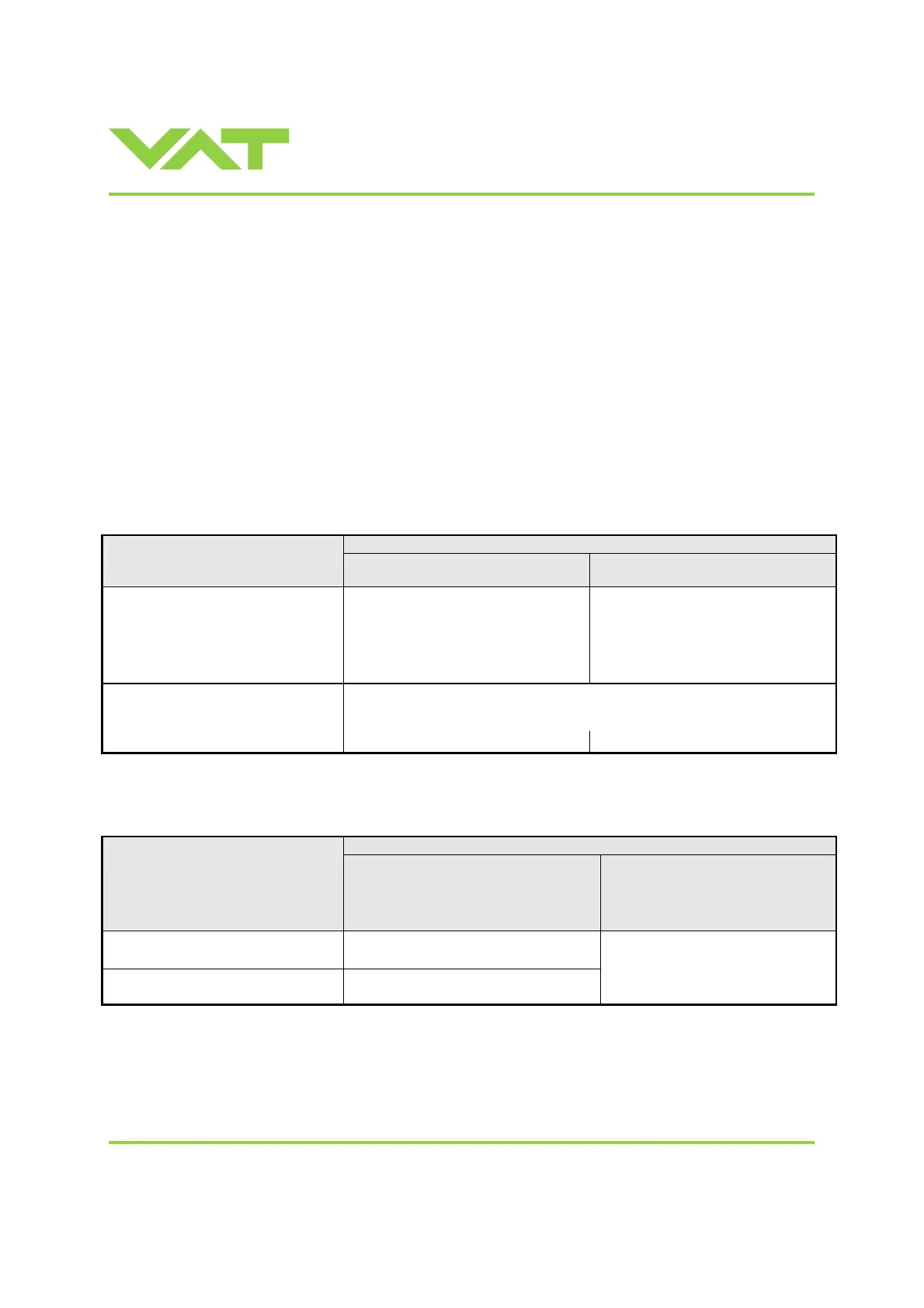
3.3 Behavior during power up
Reaction of valve:
Valve position before
power up:
Valve power up configuration = closed
(default)
Valve power up configuration = open
Closed (isolated) Valve remains closed.
Display shows alternately ‘C C’ and
‘INIT’.
Synchronization will be done when first
movement command is received.
Valve runs to max. throttle position to
detect the limit stops to synchronize.
Display shows configuration of product
resp. ‘SYNC’ until synchronization is
done.
Valve position after power up is open.
Valve runs to max. throttle position to detect limit stop for synchronization.
Display shows configuration of product resp. ‘SYNC’ until synchronization is
done.
All other than closed (not isolated)
Valve position after power up is closed
Valve position after power up is open
Refer also to chapter «Display information».
3.4 Behavior in case of power failure
Reaction of valve:
Valve position before
power failure:
Without Power Failure Option (PFO)
650 . . - . . G . - . . . .
650 . . - . . A . - . . . .
650 . . - . . T . - . . . .
650 . . - . . V . - . . . .
With Power Failure Option (PFO)
650 . . - . . H . - . . . .
650 . . - . . C . - . . . .
650 . . - . . U . - . . . .
650 . . - . . W . - . . . .
Closed (isolated) Valve remains closed.
Valve open or in any intermediate
position
Sealing ring moves down and blocks the
pendulum plate at the current position.
Valve will close or open depending
on valve configuration *).
Default is not defined.
Display indicates F.
*) Provided that battery pack of the VAT controller is charged. Charging time after power up is 2 minutes max..
All parameters are stored in a power fail save memory.

 Loading...


