Installation, Operating & Maintenance Instructions
Series 650 DN 100-250 (I.D. 4“ - 10”), CC-Link
VAT Vakuumventile AG, CH-9469 Haag, Switzerland
Tel +41 81 771 61 61 Fax +41 81 771 48 30 CH@vatvalve.com www.vatvalve.com
280672EB
2010-12-15
32/94
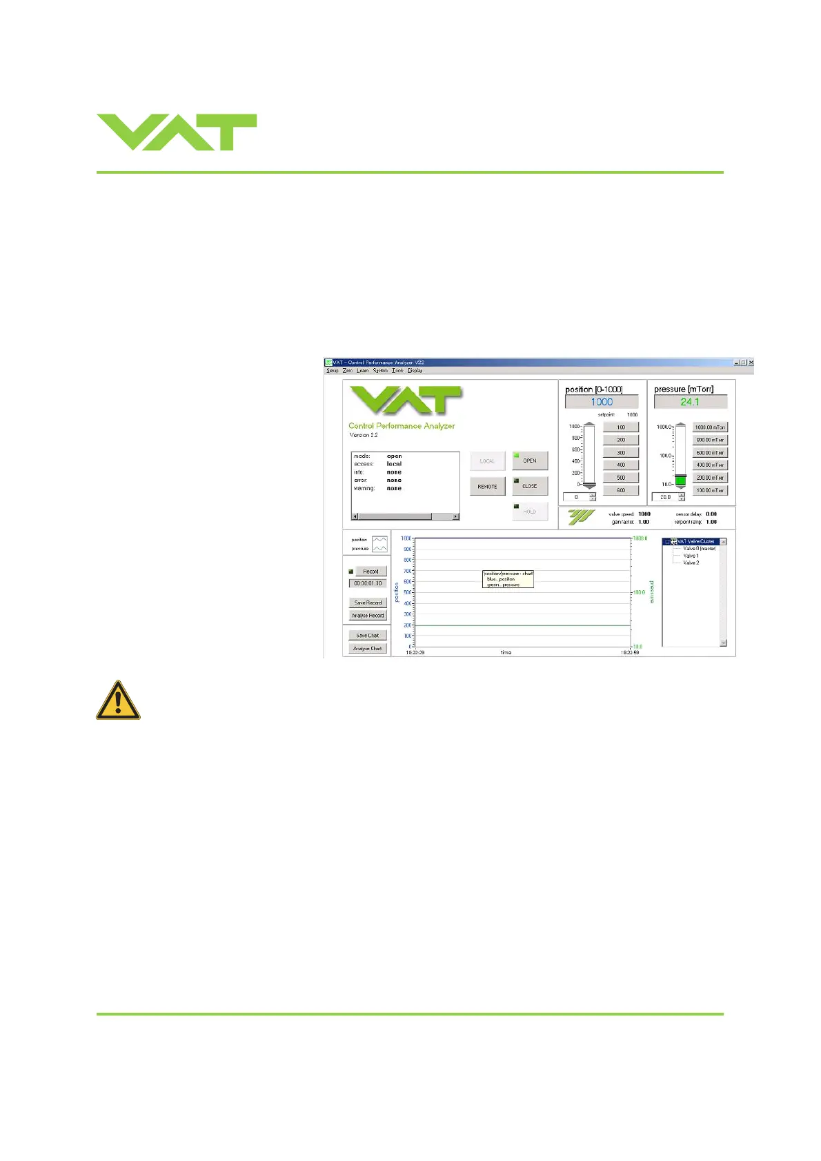
3.1.5 Local operation
Local operation means that the valve is operated via the service port using a computer or the Service Box 2. When using
a computer, a service cable and a software from VAT are required. You can either download our freeware 'Control View'
from
www.vatvalve.com or purchase our 'Control Performance Analyzer'.
These software are beneficial especially for setup, testing and maintenance.
How to start: Connect service cable, start software and push button ‘LOCAL’ to enable for operation. Then enter menu
Setup/Sensor and do sensor configuration according to your application to make sure that you get the correct pressure
displayed.
‘Control view’ supports:
- parameter setup
- manual control
- numeric monitoring
- basic diagnostic
'Control Performance Analyzer'
supports:
- parameter setup
- manual control
- sequence control
- numeric and graphical
monitoring
- data recording
- data analysis
- advanced diagnostic
When communication to service port is interrupted the valve will change to remote operation.
So when service cable will be disconnected or software will be shut down, the valve returns
automatically to remote operation.
This may result in an immediate movement of the valve depending on remote control.
Refer to «Spare parts / Accessories» for ordering numbers of service cable, software and Service Box 2.
3.1.6 Remote operation
This product is equipped with a CC-Link interface to allow for remote operation. See section «CC-Link Interface» for
details. ‘Control View’ software, 'Control Performance Analyzer' software or 'Service Box 2' may be used for monitoring
during remote control.
Note: In case ‘Control View’ or ‘Control Performance Analyzer’ software is connected to valve make sure ‘REMOTE’
button is pushed to enable for remote operation. In case Service Box 2 is connected to valve make sure the LED on
button ‘LOCAL’ is OFF for remote operation.

 Loading...


