Home
VAT
Control Unit
650 Series
VAT 650 Series User Manual
4
of 1
of 1 rating
94 pages
Give review
Manual
Specs
To Next Page
To Next Page
To Previous Page
To Previous Page
Loading...
Install
ation, Op
erating & Main
tenance In
struct
ions
Series
650 DN 100-250 (I
.D. 4“
- 10”), CC-Li
nk
VAT Vakuumv
entile AG, CH
-9469 Haag,
Switz
erland
Tel +41
81 771 61 61
Fax +41 81 771 48 30
CH@vatvalve.com
ww
w.vatvalve.com
280672
EB
2010-12-15
89/94
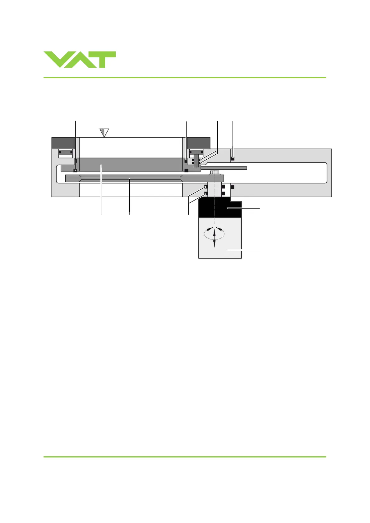
6 Dr
aw
ing
3
2
5
1
7
6
4
8
9
88
90
Table of Contents
Table of Contents
3
Use of Product
5
Technical Data
5
Installation
8
Unpacking
8
Installation into the System
8
Tightening Torque
10
Mounting with Centering Rings
10
Mounting with O-Ring in Grooves
11
Admissible Forces
11
Requirements to Sensor Connection
12
Electrical Connection
13
Ground Connection
13
Sensor Supply Concepts
14
Power and Sensor Connection (+24 VDC Sensors)
15
Power and Sensor Connection (±15 VDC Sensors) Without Optional SPS Module
17
Power and Sensor Connection (±15 VDC Sensors) with Optional SPS Module
19
Power Connection for Slave Valve Only
20
CC-Link Interface Connection
21
Logic I/O
26
Service Port Connection
26
Valve Cluster Connection
27
Operation
30
Introduction
30
Individual Valve Control
31
Individual Valve Status
31
Freeze Mode
31
Position Offset
31
Local Operation
32
Remote Operation
32
Safety Mode
33
Operation under Increased Temperature
33
Behavior During Power up
33
Behavior in Case of Power Failure
33
Display Information
34
CC-Link Leds
36
Setup Procedure
37
Cluster Address Configuration
37
CC-Link Configuration
41
Valve and Sensor Configuration
46
Zero
48
Learn
49
Close Valve
50
Open Valve
50
Position Control
51
Pressure Control
51
Tuning of Control Performance
52
CC-Link Interface
56
Schematics
56
Digital Input
57
Digital Output
57
CC-Link Handshaking
58
Location of the Handshaking Bits
59
Example of the Handshaking by a PLC-Program
60
OUTPUT Buffer (Master PLC)
61
INPUT Buffer (Master PLC)
65
Communication and Timing Control between Master (PLC) and Station (Valve)
71
PRESSURE and SENSOR READING Allocation
72
Trouble Shooting
73
Additional CC-Link Warning
75
Maintenance & Repairs
76
Maintenance Procedures
77
Option Board
84
Durability of Power Fail Battery
84
Retrofit / Replacement Procedure
85
Drawing
89
Spare Parts
90
Control Unit
90
Valve Unit
91
Accessories
92
Centering Ring with Viton O-Ring
93
Warranty
94
4
Based on 1 rating
Ask a question
Give review
Questions and Answers:
Need help?
Do you have a question about the VAT 650 Series and is the answer not in the manual?
Ask a question
VAT 650 Series Specifications
General
Brand
VAT
Model
650 Series
Category
Control Unit
Language
English
Related product manuals
VAT 653 Series
129 pages
VAT 651 Series
99 pages
VAT 65040 Series
51 pages
VAT 65048 Series
51 pages
VAT 615 Series
102 pages
VAT 613 Series
149 pages
VAT 612 Series
116 pages
VAT 642 Series
119 pages
VAT 61532-KEAQ-0001
102 pages
VAT 29 Series
13 pages
VAT 02110-BA24-0001
12 pages
VAT 95248-PAGI-0002
81 pages

 Loading...


