Installation, Operating & Maintenance Instructions
Series 650 DN 100-250 (I.D. 4“ - 10”), CC-Link
VAT Vakuumventile AG, CH-9469 Haag, Switzerland
Tel +41 81 771 61 61 Fax +41 81 771 48 30 CH@vatvalve.com www.vatvalve.com
280672EB
2010-12-15
13/94
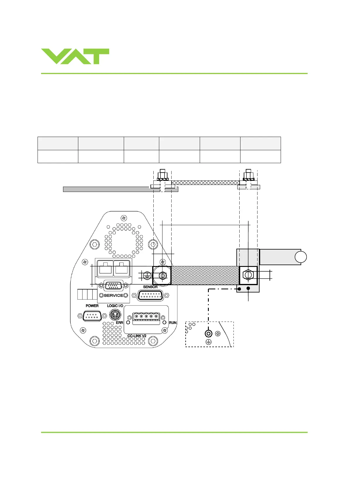
2.6 Electrical connection
2.6.1 Ground connection
Recommendation for ground strap between controller and system (chassis)
Material L (Length max.) B1 (min.) B2 (min.) d1 (∅) d2 (∅)
copper tinned 200 mm 25 mm 25 mm 4.5 mm customized
Note: Connection plates of ground strap must be total plane for a good electrical contact!
Note: The connection point at chassis (PE) must be blank metal (not coated).
It is also possible to connect the ground strap at system chamber if it is well connected to PE.
Note: Avoid low chassis cross section to the system PE connection. (Min. same cross section as ground strap)
d1
B1
Controller Master Controller Slave(s)
Recommendation
ground connection
Slave: AWG 12
(3mm
2
)
System
Chassis (PE)
(Protective Earth)
B2
d2
L
Ground strap
PE

 Loading...


