Installation, Operating & Maintenance Instructions
Series 650 DN 100-250 (I.D. 4“ - 10”), CC-Link
VAT Vakuumventile AG, CH-9469 Haag, Switzerland
Tel +41 81 771 61 61 Fax +41 81 771 48 30 CH@vatvalve.com www.vatvalve.com
280672EB
2010-12-15
21/94
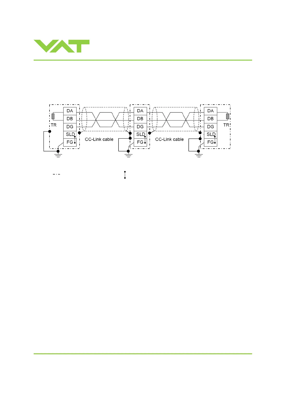
2.6.7 CC-Link interface connection
2.6.7.1 CC-Link cable installation (example)
PE = Protective Earth
= Connector housing
PE PE
= Internal connection between «SLD and FG»
Note: The valve can be defined as «first station», «…stations…» between first and last, or «last station».
If the valve at first or last station, «TR» must be installed between 1 (DA) and 2 (DB).
Note: The station type for VAT valves are: Version 2 Remote Device Station.
TR = Terminal resister (Must be compatible to used CC-Link cable version!)
first station
… stations … last station
1
2
3
4
5
1
2
3
4
5
1
2
3
4
5

 Loading...


