Installation, Operating & Maintenance Instructions
Series 650 DN 100-250 (I.D. 4“ - 10”), CC-Link
VAT Vakuumventile AG, CH-9469 Haag, Switzerland
Tel +41 81 771 61 61 Fax +41 81 771 48 30 CH@vatvalve.com www.vatvalve.com
280672EB
2010-12-15
60/94
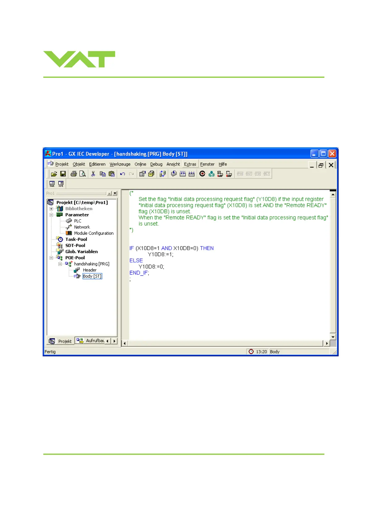
3.11.6 Example of the handshaking by a PLC-program
The following program sends an answer to the VAT CC-Link station which return a “Remote READY” flag. It is important to
correct register address is used. In this example the address for this slave station (valve) starts at 1000 (hex). So m = 100
(see capture Location of the handshaking bits). The Operational setting mode of the slave is 4 – therefore n = D.
Table 1 said RX(m+n)8 for the location of the ’Initial data processing request flag’. So the address X10D8 is used. For the
’Remote Ready’ flag the address RX(m+n)B = X10DB is used.

 Loading...


