Installation, Operating & Maintenance Instructions
Series 650 DN 100-250 (I.D. 4“ - 10”), CC-Link
VAT Vakuumventile AG, CH-9469 Haag, Switzerland
Tel +41 81 771 61 61 Fax +41 81 771 48 30 CH@vatvalve.com www.vatvalve.com
280672EB
2010-12-15
85/94
5.2.2 Retrofit / replacement procedure
ESD Precaution!
All work on the control and actuating unit has to be done under ESD protected environment to prevent
electronic components from damage!
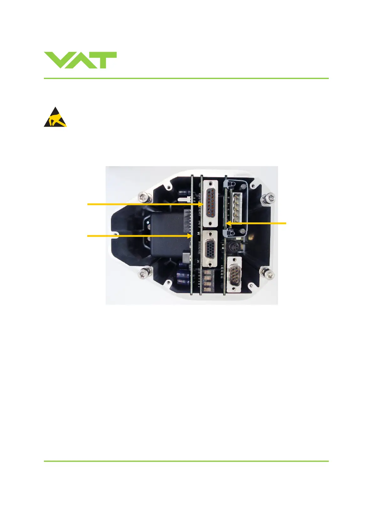
Top view on control and actuating unit with panel removed:
Note: All boards have a fixed position into control and actuating unit. It is not possible to fit a board in other position as
shown in picture above. Do not try out other positions, that may be destroy the socket of boards!
Master board
Option board
Interface board

 Loading...


