Installation, Operating & Maintenance Instructions
Series 650 DN 100-250 (I.D. 4“ - 10”), CC-Link
VAT Vakuumventile AG, CH-9469 Haag, Switzerland
Tel +41 81 771 61 61 Fax +41 81 771 48 30 CH@vatvalve.com www.vatvalve.com
280672EB
2010-12-15
71/94
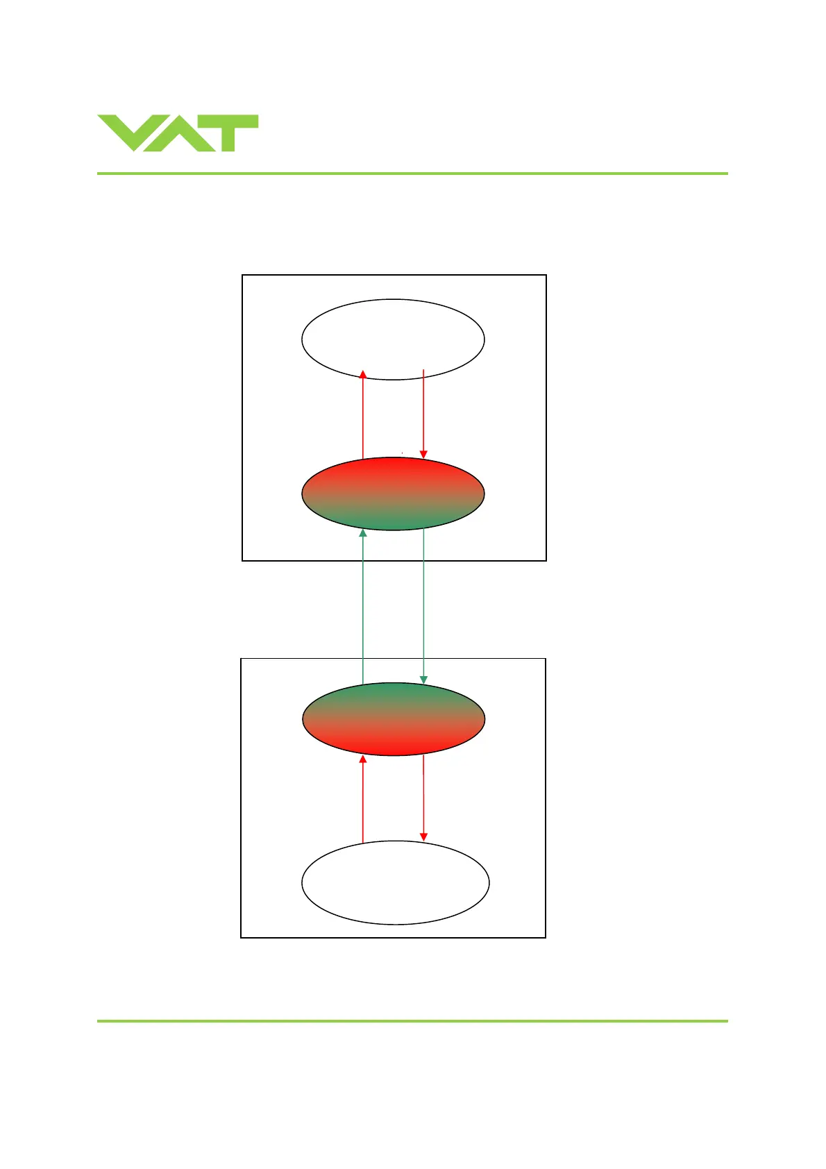
3.11.9 Communication and timing control between Master (PLC) and Station (Valve)
See chapter: «OUTPUT Buffer» > «PING PONG TX-BIT» and «INPUT Buffer» > «PING PONG RX-BIT».
For visual overview see the diagram below.
CC-Link
CC-Link buffer
Microcontroller
Ping Pong Rx = Ping Pong Tx
inverted
Slave
Station
PLC
Check if
Ping pong Rx = Ping Pong Tx
inverted
CC-Link buffer
MASTER
Station = PLC
Ping PongTx-bit
Ping PongTx-bit
Ping PongTx-bit
Ping Pong Rx-bit
Ping Pong Rx-bit
Ping Pong Rx-bit
output input
output input
Station intern Master

 Loading...


