Installation, Operating & Maintenance Instructions
Series 650 DN 100-250 (I.D. 4“ - 10”), CC-Link
VAT Vakuumventile AG, CH-9469 Haag, Switzerland
Tel +41 81 771 61 61 Fax +41 81 771 48 30 CH@vatvalve.com www.vatvalve.com
280672EB
2010-12-15
12/94
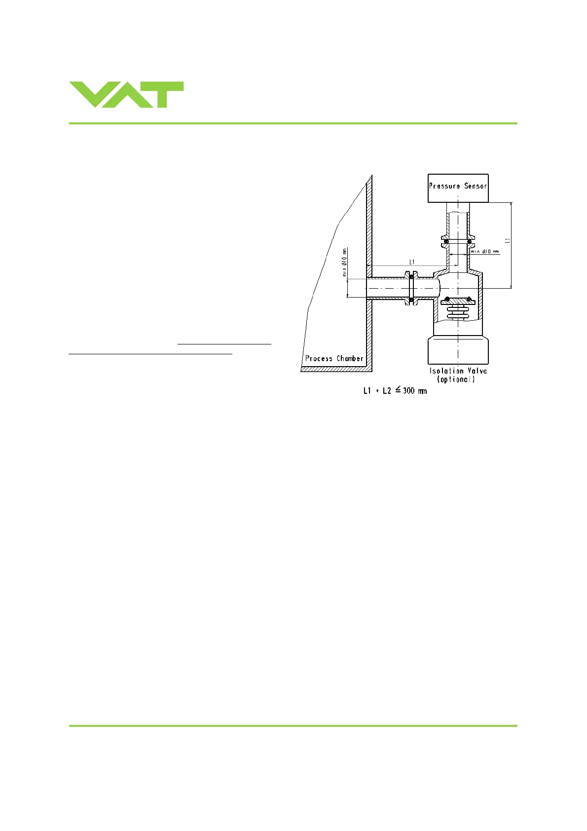
2.5 Requirements to sensor connection
To achieve fast and accurate pressure control a fast
sensor response is required.
Sensor response time: < 50ms
The sensor is normally connected to the chamber by a
pipe. To maintain that the response time is not degraded
by this connection it needs to meet the following
requirements:
Inner diameter of connection pipe: > = 10 mm
Length of connection pipe: < = 300 mm
These conductance guidelines must include all valves
and limiting orifices that may also be present.
Make also sure that there is no obstruction in front of
sensor connection port inside the chamber.
The sensor should also be mounted free of mechanical
shock and vibration.
Dynamic stray magnetic fields may introduce noise to
sensor output and should be avoided or shielded.

 Loading...


