Installation, Operating & Maintenance Instructions
Series 650 DN 100-250 (I.D. 4“ - 10”), CC-Link
VAT Vakuumventile AG, CH-9469 Haag, Switzerland
Tel +41 81 771 61 61 Fax +41 81 771 48 30 CH@vatvalve.com www.vatvalve.com
280672EB
2010-12-15
92/94
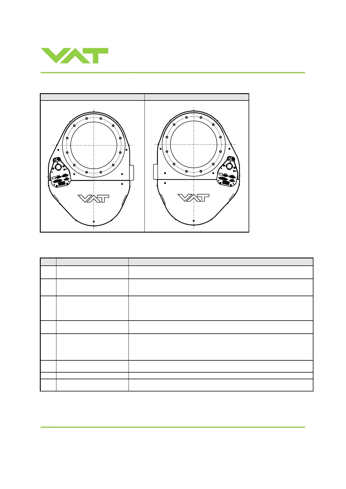
Actuator position options:
Valve with B1 actuator (standard) Valve with B2 actuator (option)
7.3 Accessories
Item Description Part number
24 VDC power supply unit
(input: 100 – 240 VAC)
369877
‘Control Performance Analyzer’
package for Windows
®
consisting
of software and cable
600SP-99LB-000
‘Control View’ software for
Windows
®
248126
free download from www.vatvalve.com
or
available on order against charge
Service cable
(PC to valve connection)
230327
free wiring information available for download from www.vatvalve.com
Connector kit consisting of:
• DB-9 female POWER plug
• DB-15 male SENSOR plug
• DB-25 male INTERFACE plug
242411
RJ-45 connector, shielded, for
stranded cable
364269
Service Box 2 601BS-29NN-000
Control panel (rack-
of Service Box 2)
602BS-29LE-000

 Loading...


