Installation, Operating & Maintenance Instructions
Series 650 DN 100-250 (I.D. 4“ - 10”), CC-Link
VAT Vakuumventile AG, CH-9469 Haag, Switzerland
Tel +41 81 771 61 61 Fax +41 81 771 48 30 CH@vatvalve.com www.vatvalve.com
280672EB
2010-12-15
36/94
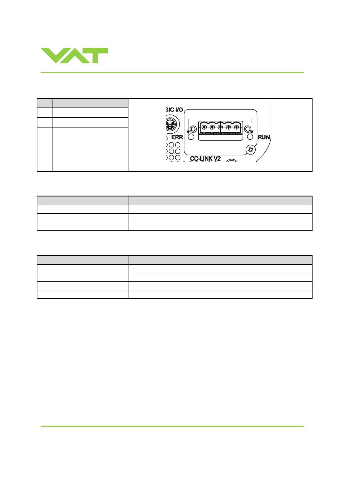
3.5.1 CC-Link LEDs
# Item
1
Error LED
2
CC-Link Interface connector
3
Run LED
Run LED (3)
State Meaning
Off No network participation, timeout status (no power)
Green Participating, normal operation
Red Major fault (FATAL error)
Error LED (1)
State Meaning
Off No error detected (no power)
Red Major fault (Exception or FATAL event)
Red, flickering CRC error (temporary flickering)
Red, flashing Station Number or Baud rate has changed since startup (flashing)
1 2 3

 Loading...


