CQ
25
Developer
Bias
RAP
-
2510
ABC
A
Switch off and unplug the copier.
Go to Flag
1
and check the developer
Press
Stop.
Wait
15
seconds. Press
Start;
bias lead for a short circuit to frame
then immediately select
Dark Input.
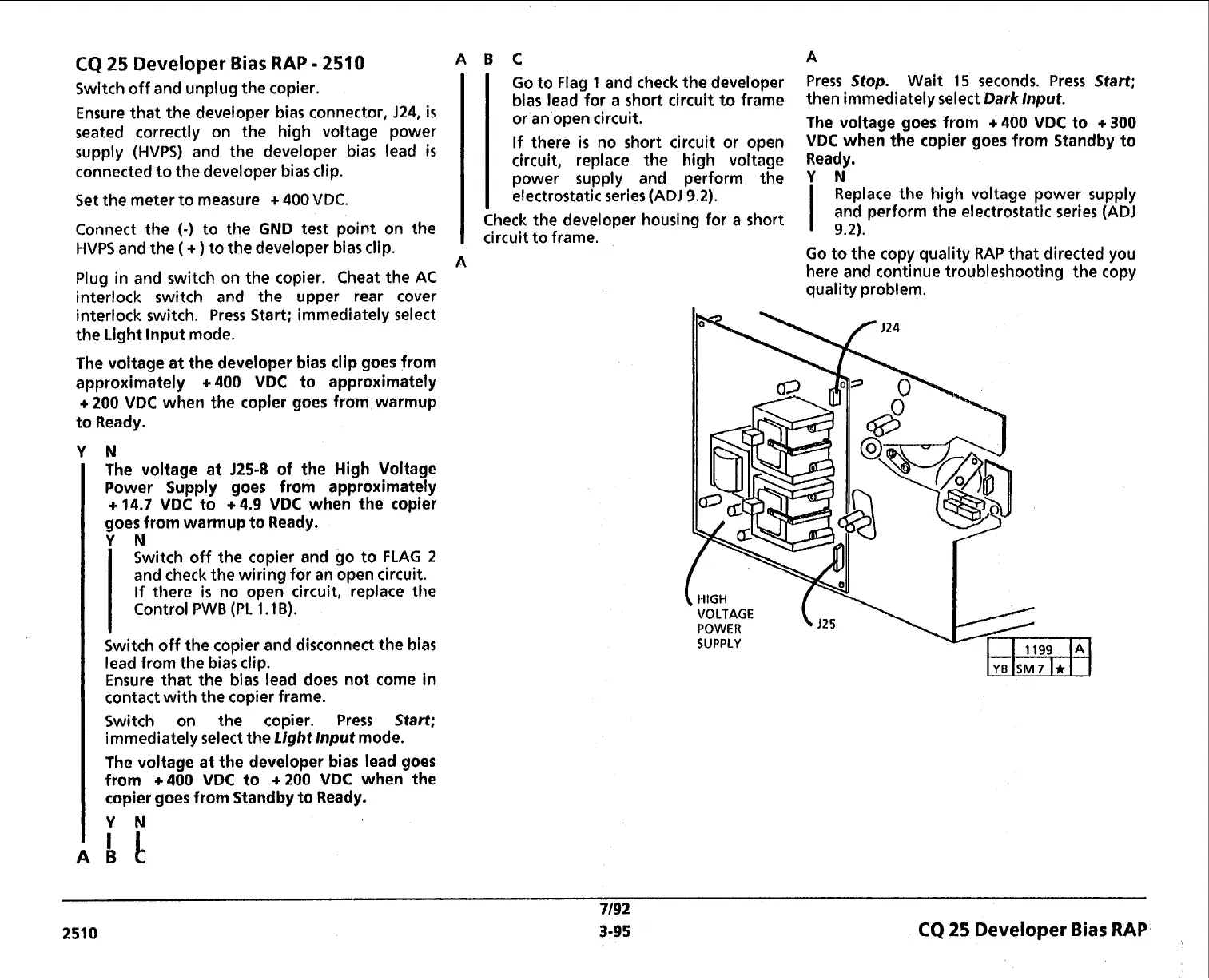
Ensure that the developer bias connector,
J24,
is
or an open circuit.
seated correctly on the high voltage power
The voltage goes from
+
400
VDC
to
+
300
supply (HVPS) and the developer bias lead
is
If there
is
no short circuit or open
VDC
when the copier goes from Standby to
connected to the developer bias clip.
circuit, replace the
high voltage Ready.
power
supply and
perform the
Y
N
Set the meter to measure
+
400
VDC.
electrostatic series
(AD1
9.2).
I
Replace the high voltage power supply
Check the developer housing for a short
and perform the electrostatic series
(ADJ
Connect the
(-)
to the
GND
test point on the
circuit
to
frame.
9.2).
HVPS and the
(
+
)
to the developer bias clip.
A
.
.
Plug in and switch on the copier. Cheat the AC
interlock switch and the upper rear cover
interlock switch. Press Start; immediately select
the Light lnput mode.
The voltage at the developer bias clip goes from
approximately
+
400
VDC
to approximately
+
200
VDC
when the copier goes from warmup
to Ready.
N
The voltage at
J25-8
of the High Voltage
Power Supply goes from approximately
+
14.7
VDC
to
+
4.9
VDC
when the copier
goes from warmup to Ready.
YN
Switch off the copier and go to FLAG
2
and check the wiring for an open circuit.
If
there
is
no open circuit, replace the
Control PWB (PL
1.1
B).
I
Switch off the copier and disconnect the bias
lead from the bias clip.
Ensure that the bias lead does not come in
contact with the copier frame.
Switch on the copier. Press
Start;
immediately select the
Light lnput
mode.
The voltage at the developer bias lead goes
from
+400
VDC
to
+200
VDC
when the
copier goes from Standby to Ready.
Go to the copy quality RAP that directed you
here and continue troubleshooting the copy
quality problem.
i
1.1
VOLTAGE
(
,25
POWER
SUPPLY
7/92
251 0
3-95
CQ
25
Developer
Bias
RAP
 Loading...