June 2014
4-18
Xerox® Phaser® 3052/3260 Service Manual
REP 1.10
Repairs
REP 1.10 Main Drive Unit
Parts List on PL 4.6
Removal
1. Switch Off the Printer and disconnect the Power Cord.
2. Remove the Left Side Cover (REP 1.2).
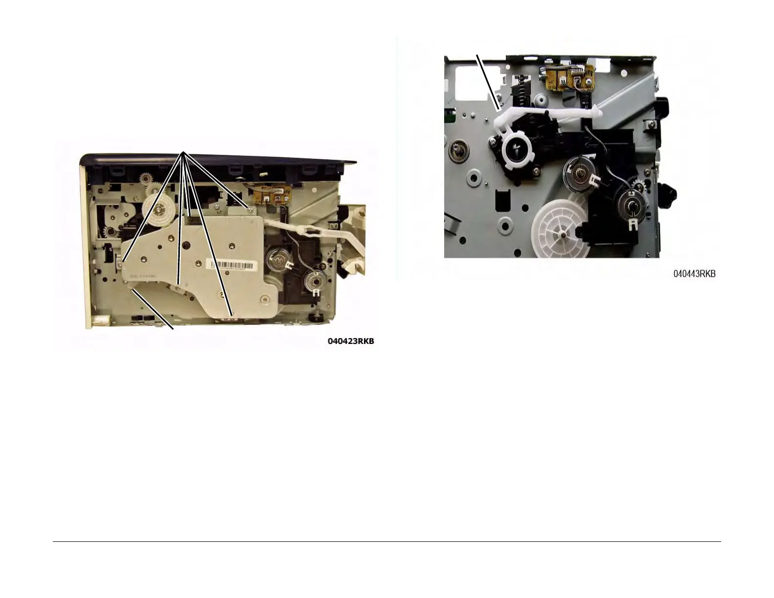
3. Remove the screws (5) from the Main Drive Unit (Figure 1).
4. Move the Fuser Drive Locking Lever to the Unlock position (Right) (Figure 1).
Remove the Main Drive Unit and the Front Door Support Arm.
Figure 1 Main Drive Unit Removal
Replacement
1. Place the Front Cover Support Arm on the Stop Bracket (Figure 2).
Figure 2 Front Cover Support Arm Placement
2. Reinstall the Main Drive Unit (5 screws).
NOTE: Make sure the Tabs (2) on the Locking Lever are inside the Frame cutouts before
moving the Fuser Drive Locking Lever to the Lock position.
3. Align the Locking Lever Tabs (2) to the cutouts in the frame (Figure 3).
4. Press in on the Locking Lever to move the Tabs into the cutouts.
Move the Locking Lever to the Lock position (Left).
5. Install the remaining components in the reverse of removal.
Screws
Locking Lever
Support Arm
 Loading...