June 2014
4-29
Xerox® Phaser® 3052/3260 Service Manual
REP 1.18, REP 1.19
Repairs
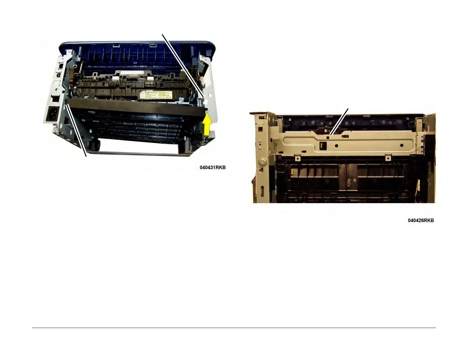
Figure 2 Duplex Assembly Pivots (Rear View)
Replacement
Install the components in the reverse of removal.
1. Insert the pivot on the left side into the hole.
2. Insert the right pivot into the frame cutout.
3. Lift and latch the front of the Duplex Assembly into position (Figure 2).
REP 1.19 Exit Sensor
Parts List on PL 4.1
Removal
1. Switch Off the Printer and disconnect the Power Cord.
2. Remove the following covers:
a. Remove the Left and Right Side Covers (REP 1.2).
b. Remove the Rear Cover (REP 1.4).
3. Remove the Fuser Module (REP 1.17)
4. Press the Latch on the underside of the frame to release the Exit Sensor Mounting Plate
from the frame (Figure 1).
Figure 1 Exit Sensor Plate Latch Release (Bottom View)
5. Remove the Exit Sensor (Figure 2):
a. Release the wires from the cable clamps.
b. Unlatch and remove the Exit Sensor, disconnect the connector.
Pivot Hole
Pivot Cutout
Latch
 Loading...