June 2014
4-31
Xerox® Phaser® 3052/3260 Service Manual
REP 1.20, REP 1.21
Repairs
Figure 2 Output Tray Full Sensor (Top Right View)
Replacement
NOTE: When re-installing the Main PWB make sure the ground screw, with large head, is rein-
stalled in the correct location.
Install the components in the reverse of removal.
REP 1.21 WNPC (WiFi) PWB
Parts List on PL 1.1
Removal
1. Switch Off the Printer and disconnect the Power Cord.
2. Remove the following covers:
a. Remove the Left and Right Side Covers (REP 1.2).
b. Remove the Rear Cover (REP 1.4).
c. Remove the Top Cover (REP 1.3).
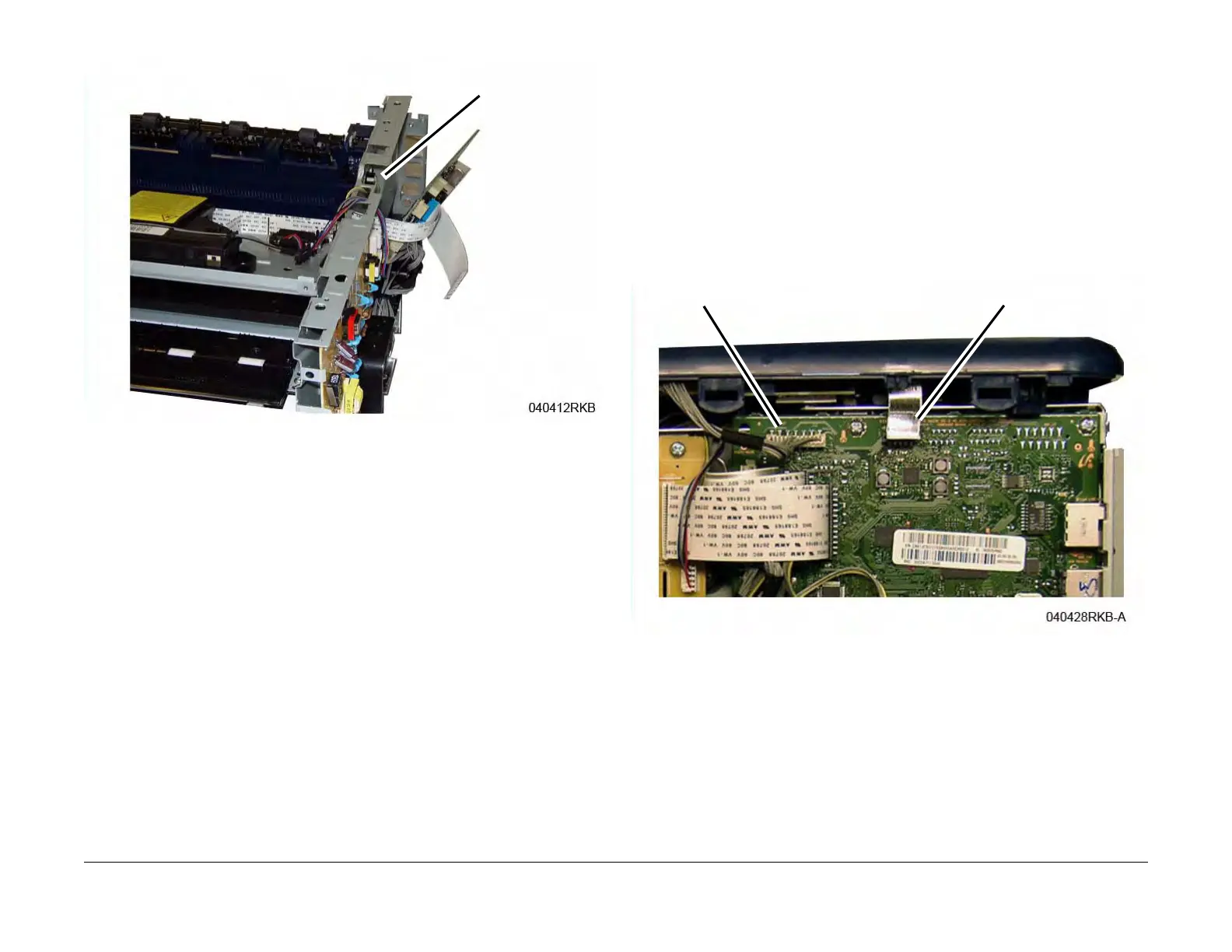
3. Disconnect the following connectors from the Main PWB (Figure 1):
a. Control Panel Connector.
b. WNPC PWB Connector.
Figure 1 Main PWB Connectors to Disconnect
Output Tray Full Sensor
WNPC Connector
Control Panel Connector
 Loading...