June 2014
4-30
Xerox® Phaser® 3052/3260 Service Manual
REP 1.19, REP 1.20
Repairs
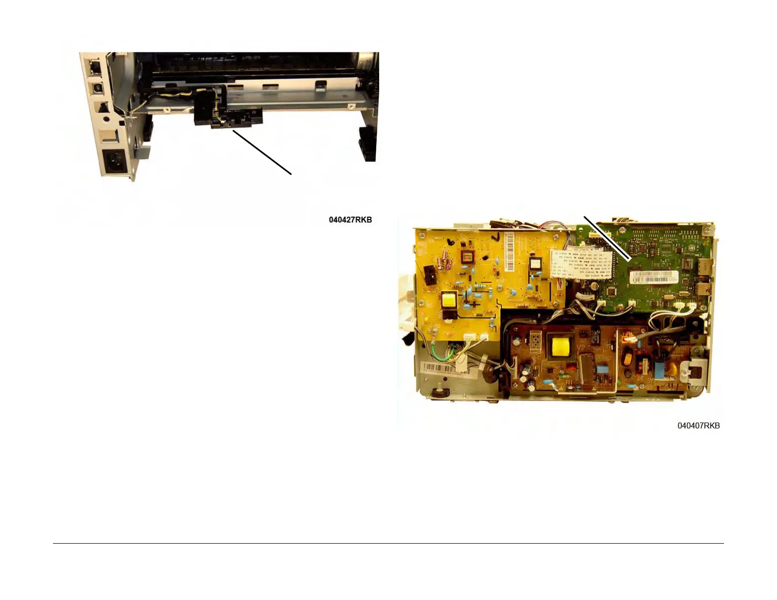
Figure 2 Exit Sensor Removal (Rear View)
Replacement
Install the components in the reverse of removal.
REP 1.20 Output Tray Full Sensor
Parts List on PL 4.3
Removal
1. Switch Off the Printer and disconnect the Power Cord.
2. Remove the following covers:
a. Remove the Left and Right Side Covers (REP 1.2).
b. Remove the Rear Cover (REP 1.4).
c. Remove the Top Cover (REP 1.3).
NOTE: Do not disconnect the connectors to the Main PWB. The PWB only needs to be moved
away from the frame to access the Output Tray Full Sensor.
NOTE: Mark the location of the Ground Screw, with larger head, so it can be re-installed in the
correct location.
3. Remove the screws (5) to move the Main PWB away from the printer frame (Figure 1).
Figure 1 Main PWB
4. Remove the Output Tray Full Sensor (Figure 2):
a. Disconnect the Sensor connector.
b. Unlatch and remove the Output Tray Sensor.
Exit Sensor
Main PWB
 Loading...