Disassembly/Assembly Procedures
Phaser® 6120 Color Laser Printer Service Manual
5-10
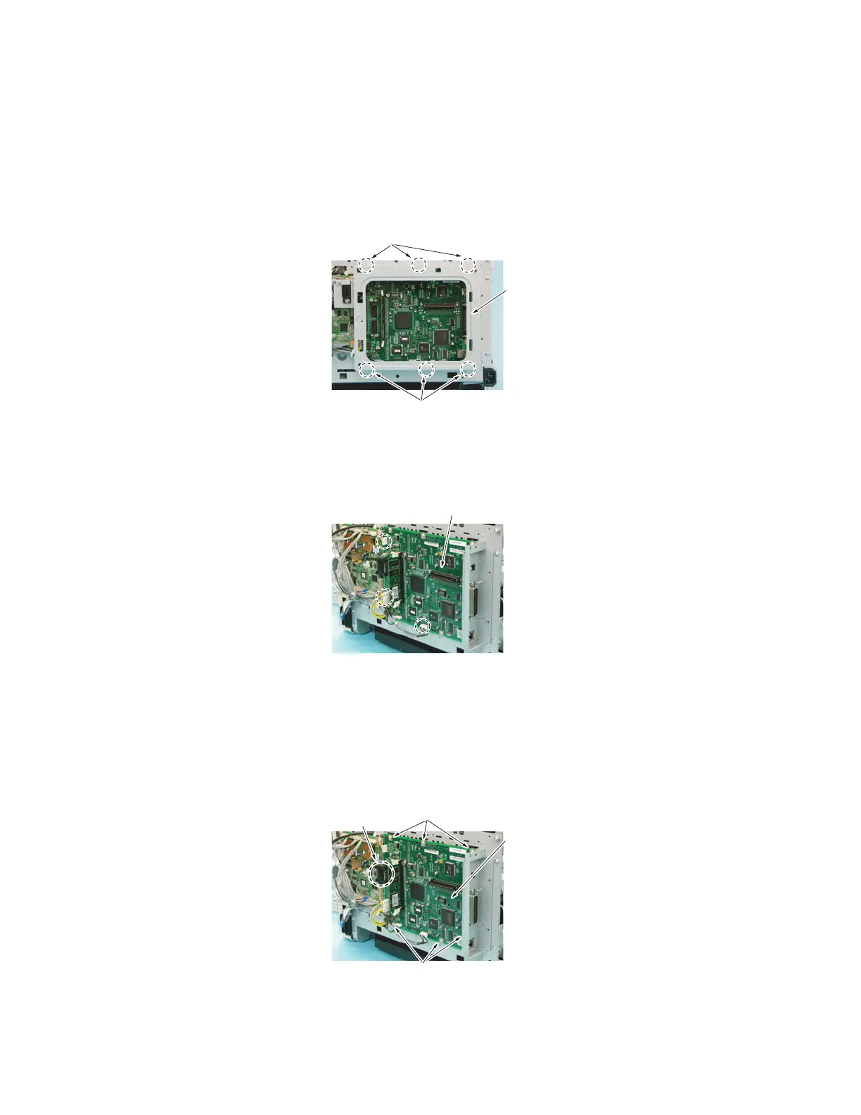
6. Remove six screws [3], and then lift the left side of the PWB-P (Image Processor Board)
protective shield [4] to remove it.
Note: For reinstallation, notice that the screw in the top middle [3] is different from the
rest of the screws.
7. Disconnect all connectors from the PWB-P (Image Processor Board) [5].
Note: If installed, remove the optional hard drive. See Hard Drive (Option) on page 5-39.
8. Remove six screws [6].
4139F2C504AA
[3]
[4]
4139F2C505AA
[5]
4139F2C506AA
[6]
[7]
[8]
[6]
 Loading...