Print Engine Theory of Operation
Phaser® 6120 Color Laser Printer Service Manual
7-4
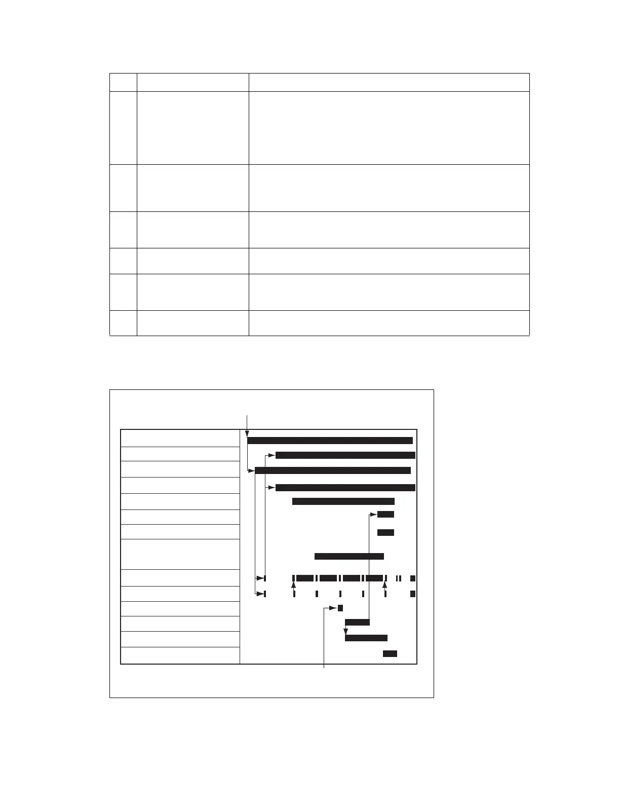
Operation Sequence
[5] Developing The toner, negatively charged in the Hopper, is attracted onto the
electrostatic latent image formed on the surface of the Photo
Conductor. It is thereby changed to a visible, developed image.
A Imaging Unit negative bias voltage is applied to the Developing
Roller, thereby preventing toner from sticking to the background
image portion.
[6] 1st Image Transfer A Imaging Unit positive voltage is applied to the backside of the
Transfer Belt, thereby allowing the visible, developed image on the
surface of the Photo Conductor to be transferred onto the Transfer
Belt.
[7] 2nd Image Transfer A Imaging Unit positive voltage is applied to the backside of the
paper, thereby allowing the visible, developed image on the surface
of the Transfer Belt to be transferred onto the paper.
[8] Paper Separation The paper, which has undergone the 2nd image transfer process, is
neutralized.
[9] Transfer Belt Cleaning A charge is applied to the Transfer Belt. By potential difference,
residual toner on the surface of the Transfer Belt is collected for
cleaning.
[10] Photo Conductor (Drum)
Cleaning
The residual toner left on the surface of the Photo Conductor is
scraped off.
Key Name Function/System
Fusing Motor (M7)
Print Request
Main Motor (M1)
Polygon Motor
Charge output
1st transfer output
2nd transfer output
2nd Transfer Roller retracted
Pressure/Retraction Solenoid
/Cleaning Blade (SL3)
Developing Motor (M3)
C-TOD
Rack Motor (M2)
Tray1 Paper Pick-up Solenoid (SL1)
Registration Roller Solenoid (SL2)
Registration Sensor (PC1)
Exit Sensor (PC7)
4139to2049e0
 Loading...