Misfeed/Jam Troubleshooting Procedures
Phaser® 6120 Color Laser Printer Service Manual
4-9
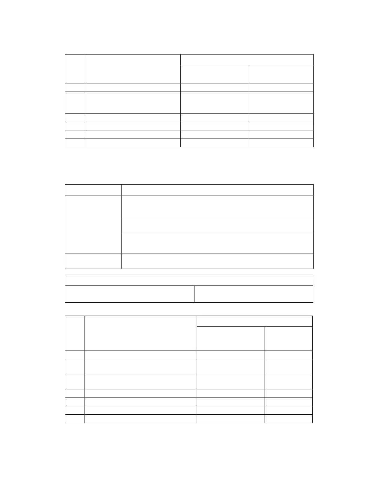
Actions
Paper Jam Fuser
Detection Timing
Actions
* for a definition of REM, see 08: Main Motor Malfunction on page 4-15.
Step Action
WIRING DIAGRAM
Control Signal
Location (Electrical
Component)
1 Initial check items. - -
2 Check the PWB-A connector for
proper connection and correct as
necessary.
--
3 PC1 sensor check. PWB-A PJ12A-3 (ON) 2-C
4 PC8 sensor check. PWB-A PJ14A-6 (ON) 2-A
5 SL2 operation check. PWB-A PJ11A-4 (REM) 2-C
6 Change PWB-A. - -
Type Description
Detection of
misfeed at fusing
section
The paper does not block the Exit Sensor (PC7) even after the lapse of a
predetermined period of time after the Registration Roller Solenoid (SL2) has
been energized.
The Exit Sensor (PC7) is unblocked within a predetermined period of time after
it has been blocked by the paper.
The Main Motor, Laser (Polygon) Motor, and Rack Motor are energized even
after the lapse of a predetermined period of time after paper information has
been created.
Detection of paper left
in fusing section
The Exit Sensor (PC7) is blocked when the Power Switch is turned ON, a cover
is opened and closed, or a misfeed or malfunction is reset.
Relevant Electrical Parts
Exit Sensor (PC7)
Registration Roller Solenoid (SL2)
PWB-A (Engine Control Board)
Print Control Board (PWB-P)
Step Action
WIRING DIAGRAM
Control Signal
Location
(Electrical
Component)
1 Initial check items. - -
2 Check the PWB-P connector for proper
connection and correct as necessary.
--
3 Check the PWB-A connector for proper
connection and correct as necessary.
--
4 PC7 sensor check. PWB-A PJ6A-3 (ON) 2-D
5 SL2 operation check. PWB-A PJ11A-4 (REM)* 2-C
6 Change PWB-P. - -
7 Change PWB-A. - -
 Loading...