Print Engine Theory of Operation
Phaser® 6120 Color Laser Printer Service Manual
7-14
Laser Timing
■ When a Ready signal is detected, a Laser ON signal is output from the PWB-P (Image
Processor Board).
■ The Laser ON signal triggers the firing of each laser Diode which illuminates the SOS
Board via the Polygon Mirror, G1 Lens, Return Mirror, G2 Lens (SOS Lens), and SOS
Mirror. This generates an SOS (Start of Scan) signal.
■ This SOS signal unifies the timing at which the laser lights are irradiated for each main
scan line.
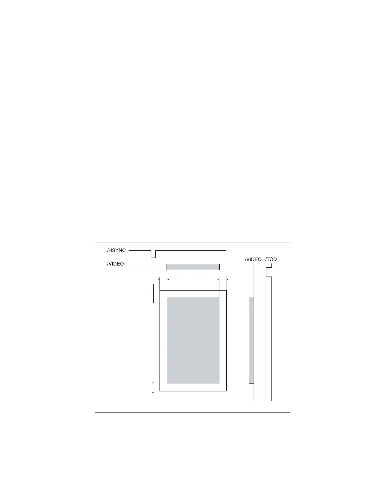
Laser Area
Main Scan Direction (CD)
■ The print start position in the CD (or scan) direction is determined by the CD print
start signal (/HSYNC) that is output from the PWB-P (Image Processor Board) and
the width of the paper.
■ The laser emission area is determined by the paper size. An area of 4 mm on both
edges of the paper is the image area boundary or margin.
Sub Scan Direction (FD or Feed Direction)
■ The print start position in the FD direction is determined by the image write start
signal (/TOD) that is output from the PWB-P (Image Processor Board) and the length
of the paper.
■ The laser emission area is determined by the paper size. An area of 4 mm on both the
leading and trailing edges of the paper is the void image area.
.
4138to2595c0
Void width: 4 mm
Void width: 4 mm
Void width: 4 mm
Void width: 4 mm
 Loading...