8-126 Phaser 7400 Color Printer Service Manual
LED Relay Board
1. Remove the Top Cover.
2. Remove the Rear Cover.
3. Disconnect the 4 LED Heads from the Engine Control Board CC, YY, MM, and
KK connectors.
4. Disconnect the CRUM Reader Board ribbon cable from the Engine Control
Board RFID connector.
5. Remove 1 (metal, 6 mm) screw that secures the cable clamp holding the LED
Head and CRUM Reader Board wiring.
6. Release the Offset Motor and Transfer Unit Fan wiring from the guides in the
LED Head Relay Board Cover.
7. Cut 1 cable tie, and then remove the LED Head cables from the guides in the
Imaging Unit Relay Board Cover.
8. Release 2 hooks that secure P492 to the LED Head Relay Board Cover.
9. Disconnect the POWER connector from the relay board.
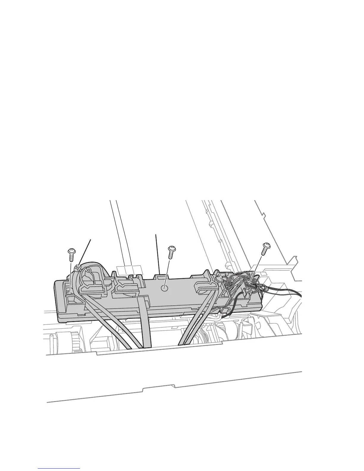
10. Remove 3 (metal, 10 mm) screws that secure the cover to the LED Assembly.
11. Release 1 hook at the front of the cover to remove the cover from the board.
12. Disconnect the KPOW, YPOW, MPOW, and CPOW connectors, and then remove
the board.
s7400-512
LED Relay Board Cover
Cable Tie
 Loading...