January 2010
xvii
Phaser 7760 Color Laser Printer
Phaser 7760 Control Panel Configuration, Image
Introduction
Revised
Control Panel Shortcuts
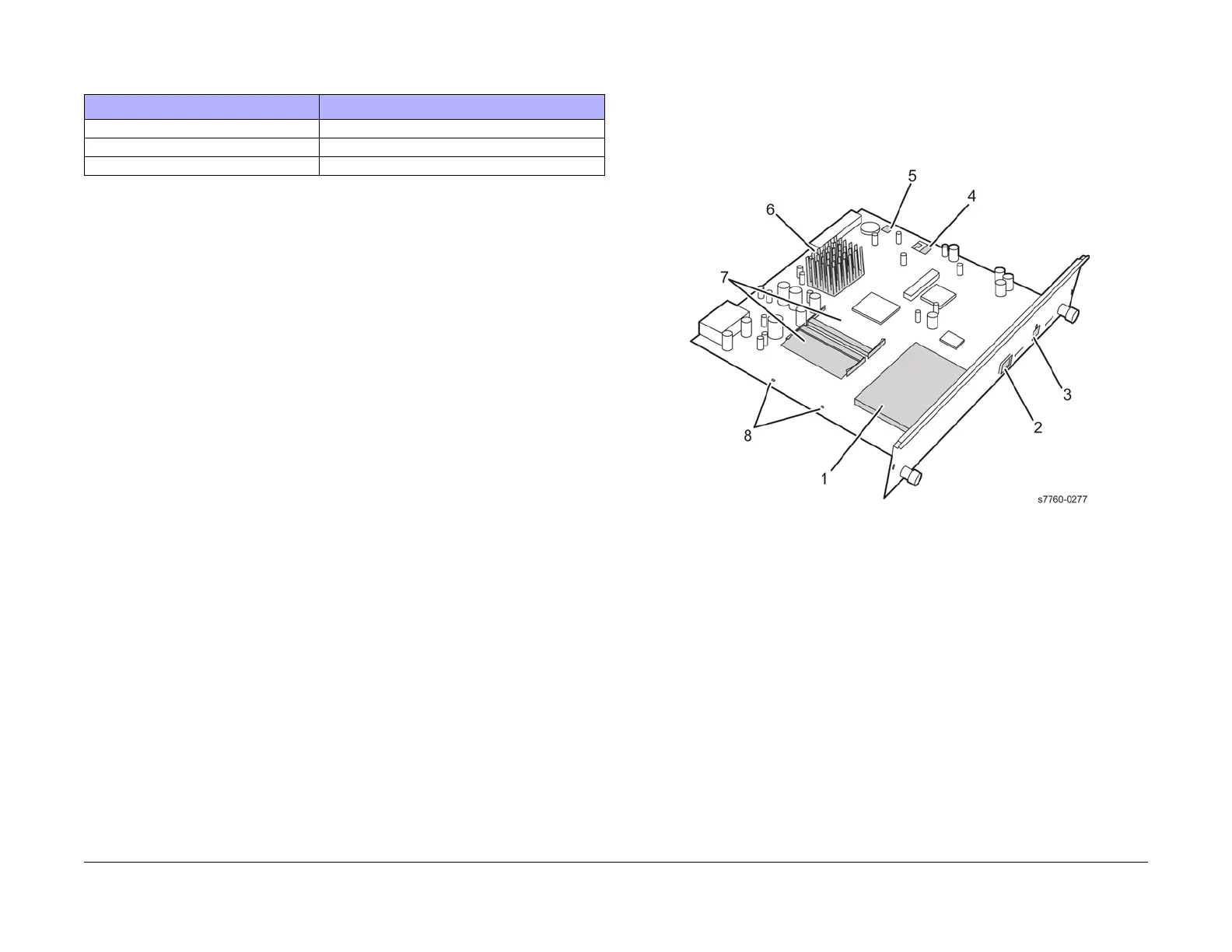
Image Processor Board and Rear Panel Host Interface
The Image Processor Board is powered by and communicates with the engine and Control
Panel through two connectors, which mate with a corresponding connector in the card cage
when the board is fully inserted. The Image Processor Board can be installed at the factory or
in the field. RAM, hard drive, and other options may be installed or changed as needed.
Figure 1 Image Processor Board
1. Hard Drive
2. USB Connector
3. Ethernet Connector
4. Config Card
5. NVRAM
6. Heat Sink
7. RAM (DDR2)
8. Health LEDs
Table 1 Short Cuts
Mode Press this selection at Power ON
Skip execution of POST diagnostics OK
Print Service Diagnostics Map INFO
Enter Service Diagnostics Menu BACK+INFO
 Loading...


