January 2010
4-5
Phaser 7760 Color Laser Printer
REP 1.5, REP 1.6
Repairs and Adjustments
Revised
REP 1.5 24V LVPS
Parts List on PL 9.1
Removal
CAUTION
PWB’s can be damaged by an electrostatic discharge. Observe all ESD procedures to avoid
component damage.
1. Remove the Rear Cover (REP 14.2).
2. Remove the Developer Fan (PL 9.1).
3. Removing the 24V LVPS (Figure 1).
a. Disconnect the 3 wiring harnesses (refer to Section 7, HVPS, +24 V LVPS T10 Plug/
Jack Locations - Figure 12).
CAUTION
5 screws with red marks secure LVPS to heat sink. Do not remove them.
b. Remove 1 screw at the top of the Bracket, loosen the 2 bottom screws and remove
the LVPS.
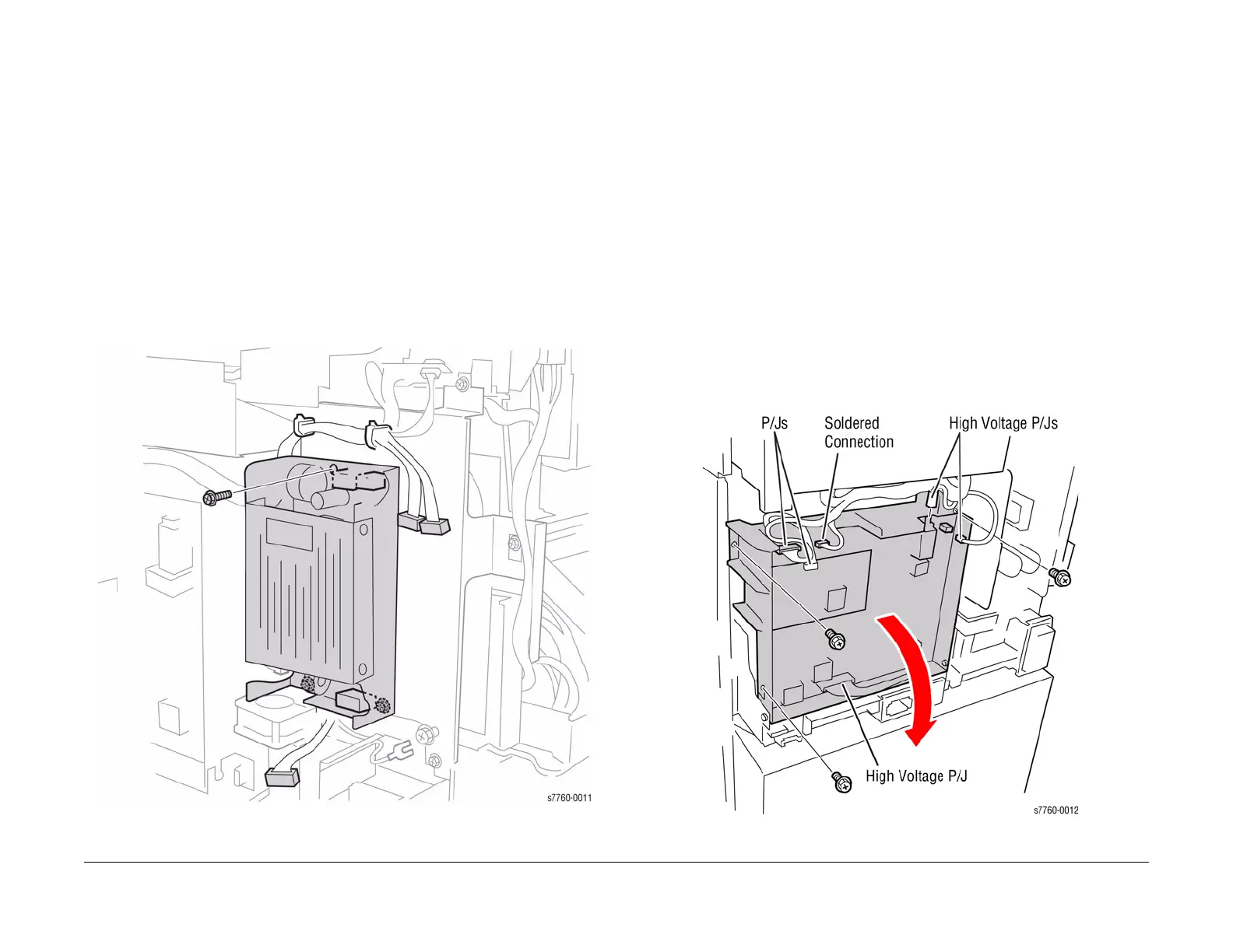
Figure 1 Removing 24V LVPS
REP 1.6 HVPS Chassis
Parts List on PL 9.1
Removal
CAUTION
HVPS can be damaged by an electrostatic discharge. Observe all ESD procedures to avoid
component damage.
1. Remove the Rear Cover (REP 14.2).
2. Remove the Developer Fan (PL 9.1).
3. Removing the HVPS Chassis (Figure 1).
a. Disconnect the 2 wiring harnesses at P/J501 and P/J574 (refer to Section 7, HVPS,
+24 V LVPS T10 Plug/Jack Locations - Figure 12). Do not disconnect the Soldered
Connection Harness.
b. Disconnect the High Voltage wiring harnesses at T205, P/J580, and P/J801 (refer to
Section 7, HVPS, +24 V LVPS T10 Plug /Jack Locations - Figure 12).
c. Loosen 1 screw and remove the Ground Wire.
d. Remove the 3 screws securing the HVPS. Remove the wiring harnesses from the
Clamps.
e. Pivot down the HVPS and engage the Stop Strap with the Frame Tab.
f. Lift the HVPS Chassis to remove.
Figure 1 Removing the High Voltage Power Supply
 Loading...


