ZCU102 Evaluation Board User Guide www.xilinx.com 112
UG1182 (v1.2) March 20, 2017
Chapter 3: Board Component Descriptions
The FMC HPC0 (J5) and FMC HPC1 (J4) VADJ pins are wired to the programmable rail
VADJ_FMC_BUS. The VADJ_FMC_BUS rail is programmed to 1.80V by default. The VADJ_FMC
derivative rail powers the XCZU9EG HP banks 64 - 67 (refer to Table 3-2, page 24).
Documentation describing PMBUS programming for the Maxim InTune power controllers is
available at the Maxim website [Ref 21]. The PCB layout and power system design meets the
recommended criteria described in the UltraScale Architecture PCB Design User Guide
(UG583) [Ref 3].
Monitoring Voltage and Current
Voltage and current monitoring and control are available for the Maxim power system
controllers through the Maxim PowerTool graphical user interface. The on-board Maxim
InTune power controllers listed in Table 3-55 are accessed through the 2x8 keyed shrouded
PMBus connector J84, which is provided for use with the Maxim PowerTool USB cable
(Maxim part number MAXPOWERTOOL001#), which can be ordered from the Maxim
website [Ref 21]. The associated Maxim PowerTool GUI can be downloaded from the Maxim
website. This is the simplest and most convenient way to monitor the voltage and current
values for the Maxim PMBus programmed power rails listed in Table 3-55.
Each PMBus programmable Maxim controller programmable is capable of reporting the
voltage and current of its controlled rail to the Maxim GUI for display to the user. A subset
of the programmable rails and two fixed rails have a TI INA226 PMBus power monitor circuit
with connections to the rail sense net and taps on a series current sense resistor. This
arrangement permits the INA226 to report the sensed parameters on the PMBus. The
subset of rails configured with the INA226 power monitors is shown in Table 3-56.
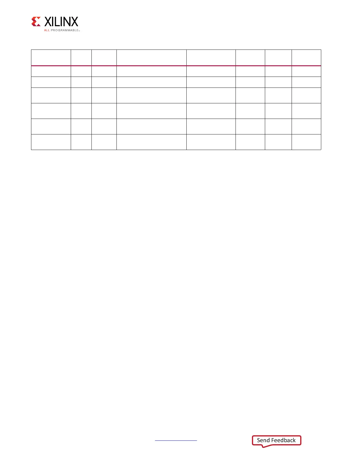
MAX8869E U143
N/A
Maxim LDO Regulator 1A UTIL_1V13 1.13V
NA
81
MAX8869E U37
N/A
Maxim LDO Regulator 1A UTIL_1V8 1.80V
NA
82
MAX15301 U49
0x1A
Maxim InTune digital POL
controller 20A
UTIL_3V3 3.30V
NA
83
MAX15303 U8
0x1B
Maxim InTune digital POL
controller 6A
UTIL_5V0 5.00V
NA
84
TPS15200 U36
N/A
Memory Vtt Sink-Souce
Regulator 3A
PS_DDR4_VTT 0.6V
NA
85
TPS15200 U35
N/A
Memory Vtt Sink-Souce
Regulator 3A
PL_DDR4_VTT 0.6V
NA
85
Table 3-55: ZCU102 Power System Devices (Cont’d)
Device Type
Ref.
Des.
PMBus
Address
Description
Power Rail Net
Name
Power Rail
Voltage
INA226
Address
Schematic
Page

 Loading...


