ZCU102 Evaluation Board User Guide www.xilinx.com 62
UG1182 (v1.2) March 20, 2017
Chapter 3: Board Component Descriptions
PMU GPI (MIO 26)
PS-side MIO 26 is reserved as an input to the PMU for indicating a warm boot. PS bank 501
MIO26 (U1.P21) is connected to the I2C0 U61 TCA6416APWR bus expander (port P04 U61.8)
through L/S U147 SN74AVC1T45. Refer the Zynq UltraScale+ MPSoC Technical Reference
Manual (UG1085) [Ref 2] for more details about the PMU interface.
DPAUX (MIO 27-30)
The Zynq UltraScale+ MPSoC provides a VESA DisplayPort 1.2 source-only controller that
supports up to two lanes of main link data at rates of 1.62 Gb/s, 2.70 Gb/s, or 5.40 Gb/s. The
DisplayPort standard defines an auxiliary channel that uses LVDS signaling at a 1 Mb/s data
rate, which is translated from single-ended MIO signals to the differential DisplayPort AUX
channel, DPAUX (see Table 3-27). The DisplayPort circuit is shown in Figure 3-22.
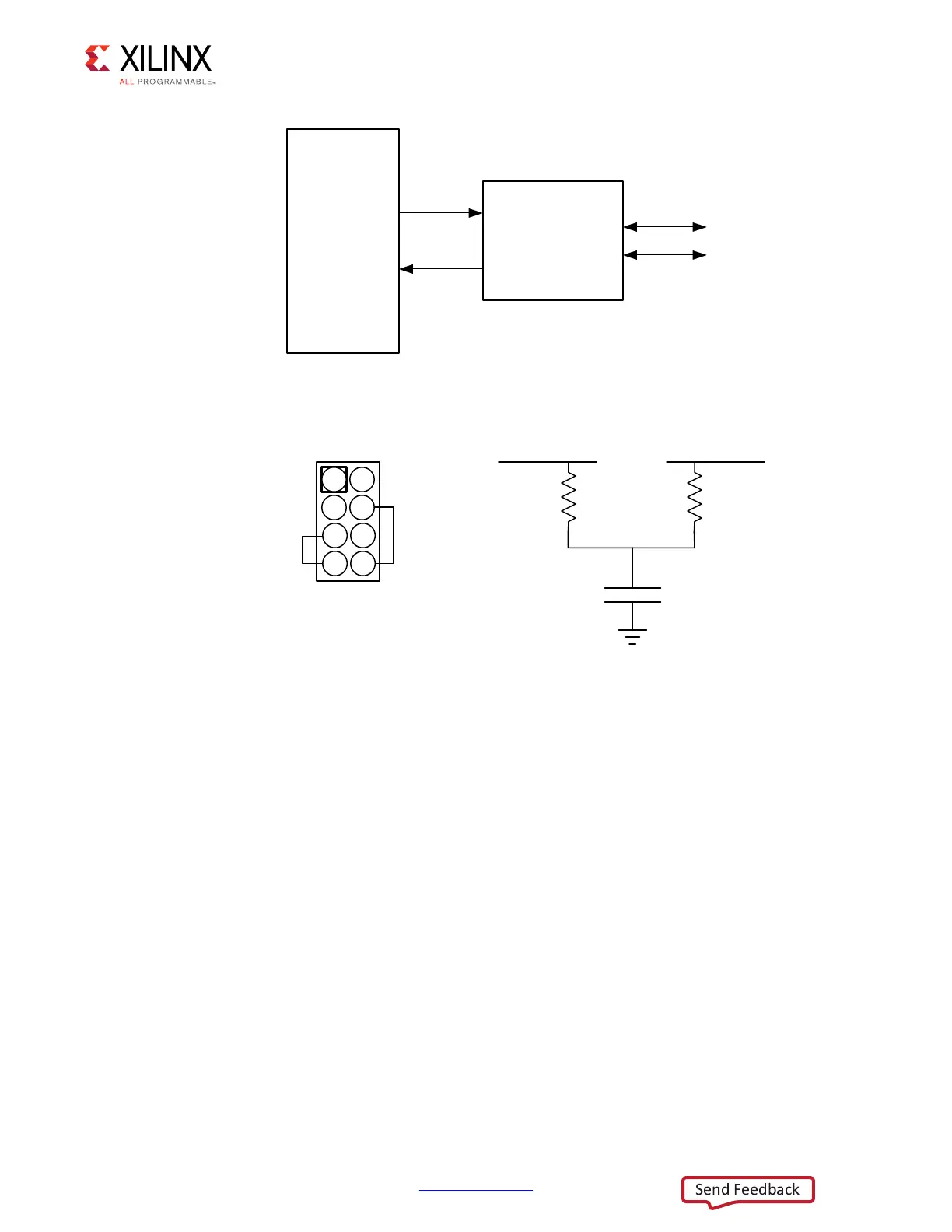
X-Ref Target - Figure 3-20
Figure 3-20: PS-Side CAN Bus Interface Diagram
X-Ref Target - Figure 3-21
Figure 3-21: PS-Side Can Bus Interface Connector
7;6( 61+9'
&$1+
&$1/
&$1B7;
&$1B5;
;
2KPV
2KPV
S)
&$1+B7(50 &$1/B7(50
&$1/B7(50
&$1+B7(50
&$1+&$1/
*1'*1'
;

 Loading...


