ZCU102 Evaluation Board User Guide www.xilinx.com 61
UG1182 (v1.2) March 20, 2017
Chapter 3: Board Component Descriptions
GPIO (MIO 22-23)
PS-side pushbutton SW19 is connected to MIO22 (pin U1.AD20). PS-side LED DS50, placed
next to the pushbutton, is connected to MIO23 (pin U1.AD19).
CAN1 (MIO 24-25)
The PS-side CAN bus TX and RX MIO pins go through TXS0104E level-translator U33 and TI
SN65HVD232 CAN-bus transceiver U122 before being presented to the user on 0.1 inch
centered 8-pin male header J98 (see Figure 3-20 and Figure 3-21).
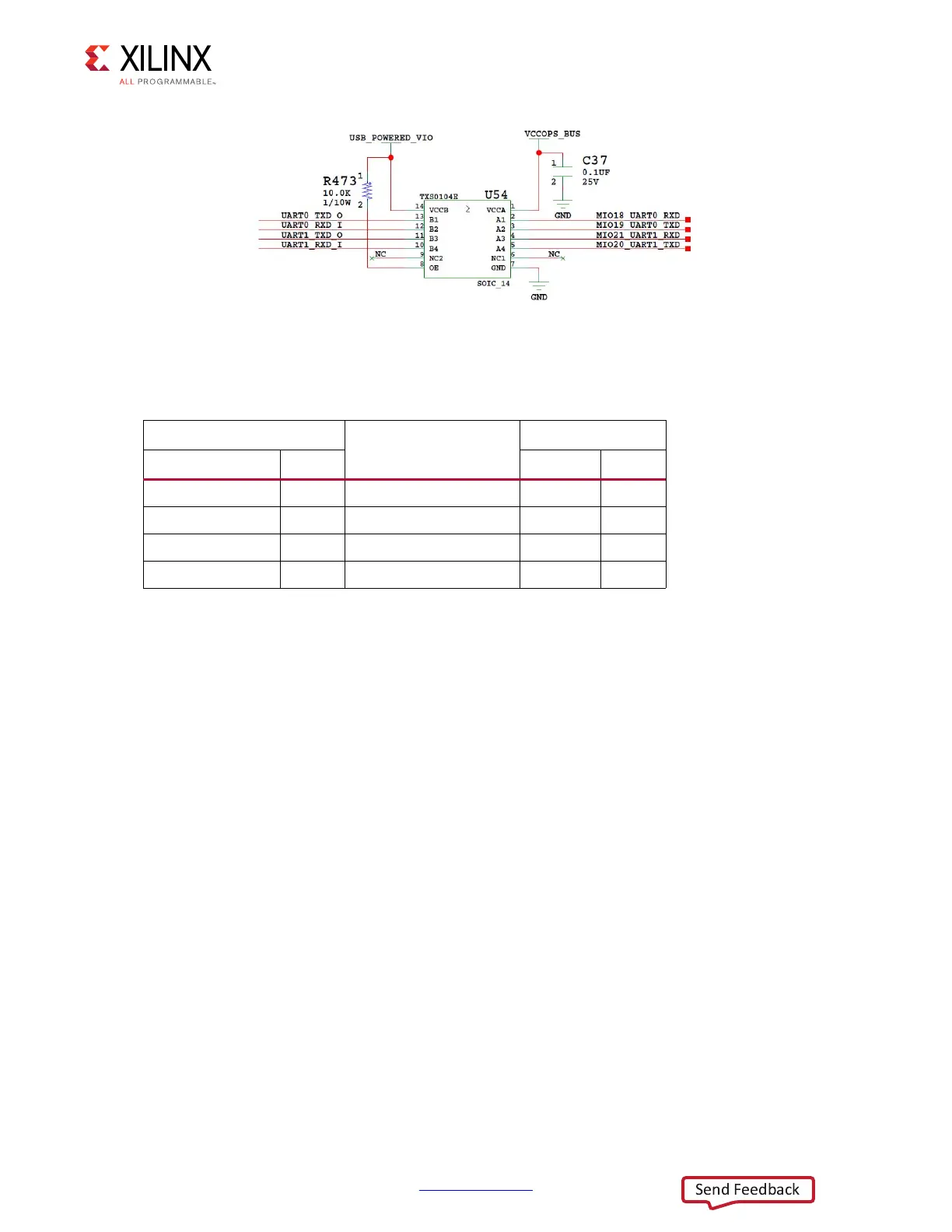
X-Ref Target - Figure 3-19
Figure 3-19: CP2108 Channel 1 PS-Side UART Interface
Table 3-26: XCZU9EG U1 to CP2108 U40 Connections via L/S U54
XCZU9EG U1
Schematic Net Name
CP2108 U40
Pin Name Pin No. Pin Name Pin No.
PS_MIO18_AE18 AE18 MIO18_UART0_RXD
TX_0 57
PS_MIO19_AL17 AL17 MIO19_UART0_TXD
RX_0 56
PS_MIO21_AF18 AF18 MIO21_UART1_RXD
TX_1 49
PS_MIO20_AD18 AD18 MIO20_UART1_TXD
RX_1 48

 Loading...


