ZCU102 Evaluation Board User Guide www.xilinx.com 74
UG1182 (v1.2) March 20, 2017
Chapter 3: Board Component Descriptions
User I2C0 Receptacle
[Figure 2-1, callout 20]
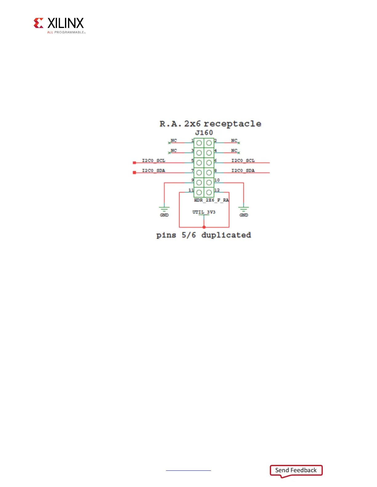
The ZCU102 evaluation board supports a PMOD 2X6 receptacle (right-angle female) J160.
Figure 3-30 shows the I2C0 PMOD receptacle J160. The I2C0 nets are a branch of the I2C0
main bus (see Figure 3-17 and I2C0 (MIO 14-15), page 54 for more details).
User I/O
[Figure 2-1, callouts 21-23]
The ZCU102 board provides these user and general purpose I/O capabilities:
• Eight user LEDs (callout 21)
°
GPIO_LED[7-0]: DS38, DS37, DS39, DS40, DS41, DS42, DS43, DS44
• 8-position user DIP Switch (callout 22)
°
GPIO_DIP_SW[7:0]: SW13
• Five user pushbuttons and CPU reset switch (callout 23)
°
GPIO_SW_[NESWC]: SW18, SW17, SW16, SW14, SW15
°
CPU_RESET: SW20
X-Ref Target - Figure 3-30
Figure 3-30: J160 PMOD I2C0 R.A. Receptacle

 Loading...


