VB3/ V5 / VB 5 series inverter
21
2-5-2
2-5-2
2-5-2
2-5-2 .
.
.
. Description
Description
Description
Description of
of
of
of terminals
terminals
terminals
terminals on
on
on
on control
control
control
control panel
panel
panel
panel
1. Functions of CN1 terminal are shown as below in Table 2-3 :
Table
Table
Table
Table
2-3
2-3
2-3
2-3 Function
Function
Function
Function of
of
of
of CN1
CN1
CN1
CN1 on
on
on
on control
control
control
control panel
panel
panel
panel
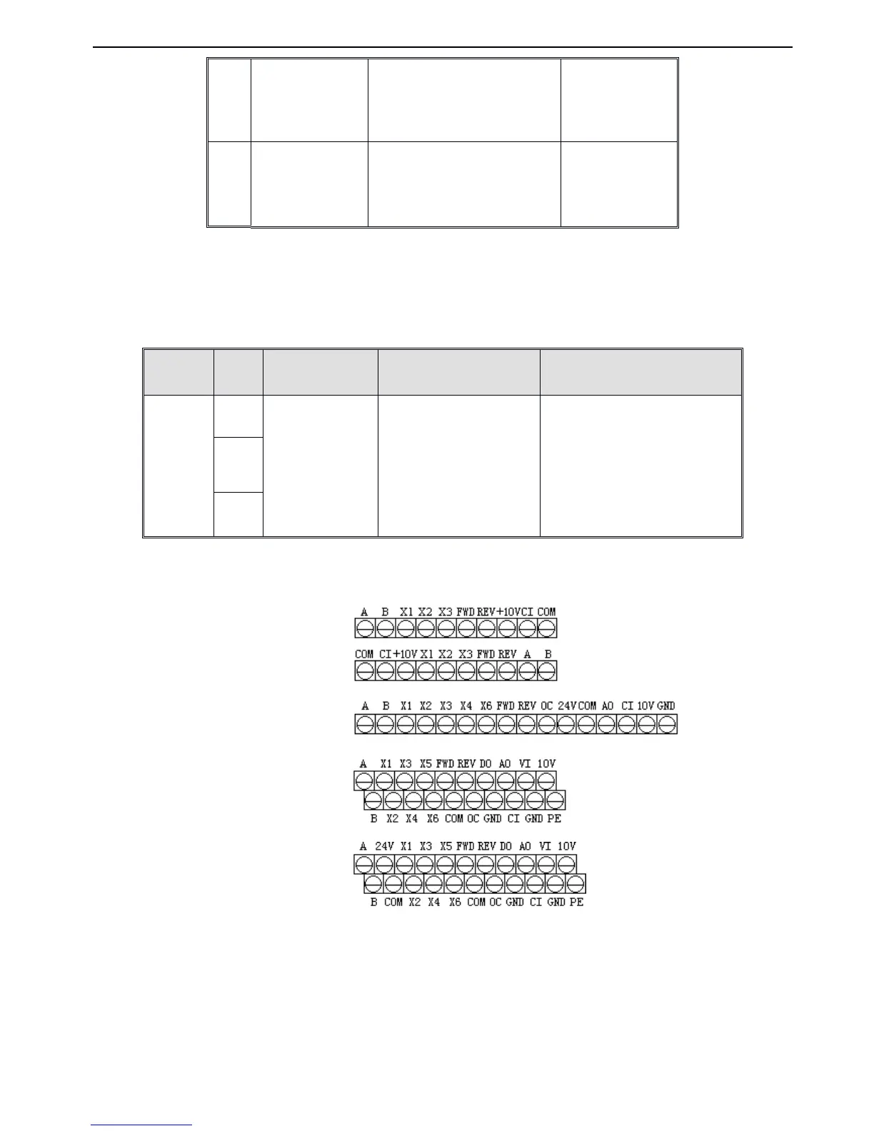
2. Control circuit terminals CN2
Fig.
Fig.
Fig.
Fig. 2
2
2
2 -
-
-
- 5
5
5
5 Terminals
Terminals
Terminals
Terminals on
on
on
on control
control
control
control panel
panel
panel
panel
An a log output
terminal AO output
1 - 2 connect : 4~20mA , AO
terminal output s current signal
2 - 3 connect : 0~10V , AO terminal
output s voltage signal
CI current/voltage
input modes selection
1
-
2 connect
:
V
side
:
0~10V
volta
ge
signal
2 - 3 connect : I side : 4~20mA
current signal
Inverter
Multi - function
relay output terminals
Inverter
Multifunctional relay output
terminals.
Please
refer to
terminal function parameters
P4.11
and description of output
terminals
TA-TC:
normal close,
TA-TB:
normal open
Contact Capacity :
AC250V/2A (COS Φ =1)
AC250V/1A (COS Φ =0.4)
DC30V/1A
VB3 series single phase 0.4 ~ 0.75KW
VB5 series single phase 1.5KW
VB5 series three phase 1.5 ~ 3.7KW
VB5 series three phase 5.5 ~ 7.5KW
 Loading...