59
Fig.
Fig.
Fig.
Fig. 4
4
4
4 -
-
-
- 7
7
7
7 V/F
V/F
V/F
V/F curve
curve
curve
curve
Fig.
Fig.
Fig.
Fig. 4
4
4
4 -
-
-
- 8
8
8
8 U
U
U
U ser-defined
ser-defined
ser-defined
ser-defined V/F
V/F
V/F
V/F curve
curve
curve
curve
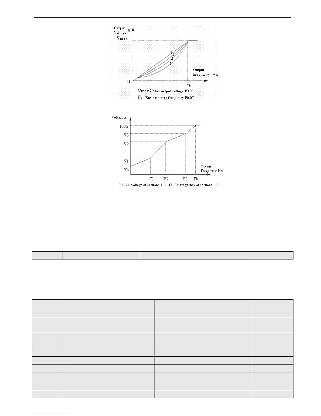
When P0.22 is set to 4 , you can define V/ F curve via modifying (V1 , F1)
,
(V2 , F2)
,
(V3 , F3) to satisfy the special load
requirement
,
as shown in Fig.4-8
.
Torque boost is suitable for user-defined V/F curve.In Fig.4-8
.
Vb = Torque boost ( P0.09 ) × V1
4-2-2
4-2-2
4-2-2
4-2-2
.
.
.
.
Parameters
Parameters
Parameters
Parameters of
of
of
of reference
reference
reference
reference frequency
frequency
frequency
frequency ( Group
Group
Group
Group P1
P1
P1
P1 )
It is the constant time of the filter that is for internal sample picking
by
inverter when reference frequency is set
by
external
analog channel.When the wire is too long or the interference is serious which can lead to reference frequency becomes
wavy, you can increase filter time to improve the situation. The bigger the time constant is
,
the higher the immunity level,
but the response time is prolonged with the increase of the time constant. That is, the smaller the time constant is, the shorter
the response time, but the lower the immunity level.
 Loading...