24
F
F
F
F ig.
ig.
ig.
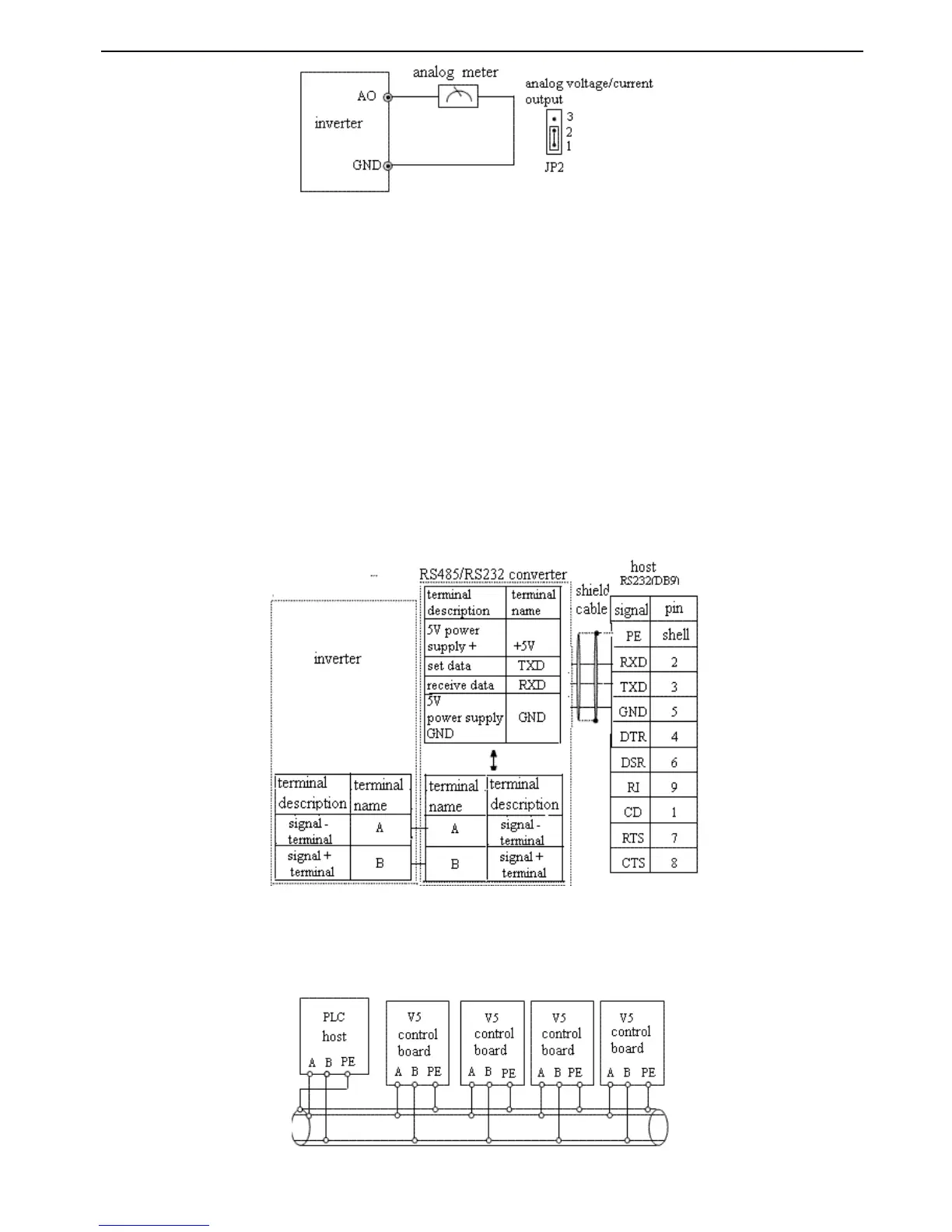
ig. 2-8
2-8
2-8
2-8 Analog
Analog
Analog
Analog output
output
output
output wiring
wiring
wiring
wiring
Note
Note
Note
Note :
:
:
:
(1) When us ing analog input, you can connect filter capaci tor or common mode inductor between VI and GND, or CI and
GND.
(2) Because analog input signal is easily interfer ed
by
outside
,
the shield cable is required
,
the cable length must be short
and the shield layer must be grounded well.
2-5-4
2-5-4
2-5-4
2-5-4
.
.
.
.
Connection
Connection
Connection
Connection of
of
of
of communication
communication
communication
communication terminals
terminals
terminals
terminals
The communication port of this inverter is standard RS485 port.
With the following wiring method s
,
you can buildup control system of one host with one slave or one host with several
slaves. Also, you can realize the functions such as real time monitor, remote control, high level automation and others for
the inveter with the host (PC or PLC) software.
Connection of inverter
’
s RS485 port and the host:
Fig.
Fig.
Fig.
Fig. 2-9
2-9
2-9
2-9 RS485
RS485
RS485
RS485 -
-
-
- (RS485/232)
(RS485/232)
(RS485/232)
(RS485/232) -
-
-
- RS232
RS232
RS232
RS232 cable
cable
cable
cable connection
connection
connection
connection
More than one inve r ter s can be connected through RS485 with the PLC(or PC) as the host, as shown in Fig.2-10; Also,
you can select one inveter as host and the other inverters as slaves, as shown in Fig. 2-11.Because with increasing of the
inverter
’
s quantities
,
the communication system will be interfered easier, the following wiring is recommended.
Fig.
Fig.
Fig.
Fig. 2-10
2-10
2-10
2-10 Connection
Connection
Connection
Connection of
of
of
of PLC
PLC
PLC
PLC and
and
and
and inverters
inverters
inverters
inverters
 Loading...