74
20
20
20
20 : Set running time arriving .
.
.
. When the accumulat ing time ( P3.40 ) arrive the reference time (P3.39), an indication signal
will be output.
This parameter is the additional definition of No.
1
function in Table4-6. As shown in Fig.4-26, when the output frequency
of inverter is within the detecting range of reference frequency, pulse signal will be output.
Fig
Fig
Fig
Fig 4-26
4-26
4-26
4-26 Frequency
Frequency
Frequency
Frequency arriving
arriving
arriving
arriving signal
signal
signal
signal
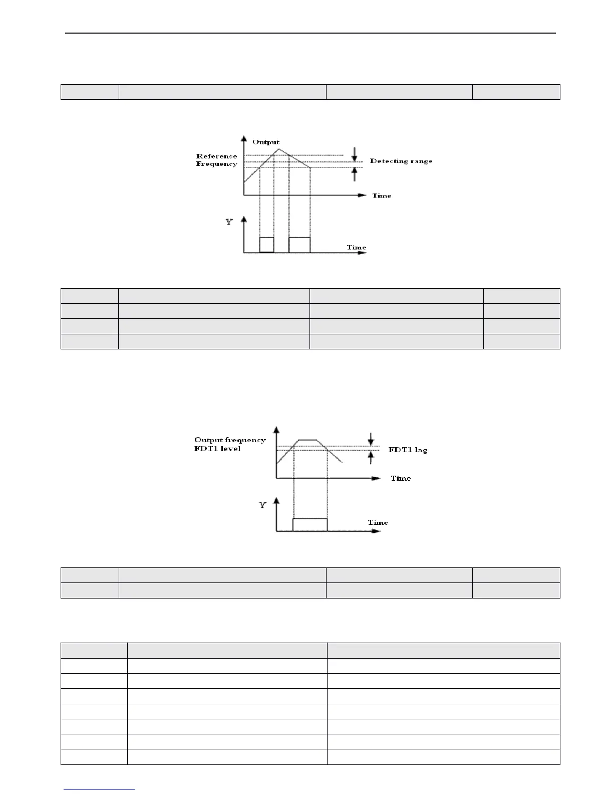
P4.13 ~ P4.14 is the additional definition of No.2 function in Fig.4-6, P 4.15 ~ P4.16 is the additional definition of No.3
function in Fig.4-6
,
The both have the same usage and the following take P4.13 ~ P4.14 as an example to introduce.When
the output frequency over a certain frequency( FDT1 level )
,
indication signal will be output until the output frequency fall to
the value which is lower than the certain frequency (FDT1 level - FDT1 lag ) , as shown in Fig. 4-27 .
Fig.
Fig.
Fig.
Fig. 4-27
4-27
4-27
4-27 FDT
FDT
FDT
FDT level
level
level
level
Table
Table
Table
Table
4-7
4-7
4-7
4-7 Output
Output
Output
Output terminals
terminals
terminals
terminals
 Loading...