75
As to the analog output of AO, you can adjust the output gain to change the measuring range or calibrate the meter.
0
0
0
0 : 4
4
4
4 ~ 20mA
20mA
20mA
20mA
1
1
1
1 : 0
0
0
0 ~ 10V
10V
10V
10V
Refer to Table 4-7 for function selection of DO output terminal .
This parameter defines the max output frequency of DO terminal .
P4.22
,
P4.23 are the additional definition of N o.12,13 function s in table 4-6 .
Preset counting value arriving: It defines after Xi receives the relay or OC (bi-direction open-collector output terminal) will
output a signal.
For example: as shown in Fig. 4-28
,
when the eighth pulse signal is received
by
terminal Xi, OC outputs an indicating signal
and F7.33=8 at this time .
Mid counting value arriving: When Xi receives the number of pulse F7.34, OC or the relay will output a signal which will
last until preset counting value arrives.
As shown in Fig. 4-28
,
when Xi receives the 5th pulse, t he realy outputs an indication signal. It lasts until X1 receives the
8th pulse. At this time
,
P4.23
=5
.
The mid counting value will be disabled if it is bigger than preset counting value .
Fig.
Fig.
Fig.
Fig. 4
4
4
4 — 28
28
28
28 Preset
Preset
Preset
Preset counting
counting
counting
counting value
value
value
value arriving
arriving
arriving
arriving and
and
and
and Mid
Mid
Mid
Mid counting
counting
counting
counting value
value
value
value arriving
arriving
arriving
arriving
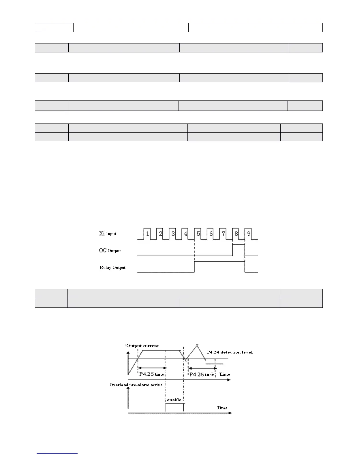
If output current over the detecting level set
by
P4.24 continuously ( Actual detecting current level = P4.24 × inverter
’
s rate
d
cur r ent
) ,
Bi-direction open-collector will output available signal after the delay time set
by
P4.25(refer to Fig.4-29 and
P4.11 for details) .
Fig.
Fig.
Fig.
Fig. 4-29
4-29
4-29
4-29 Overload
Overload
Overload
Overload pre-alarm
pre-alarm
pre-alarm
pre-alarm
 Loading...