25
(Inverters
(Inverters
(Inverters
(Inverters and
and
and
and motors
motors
motors
motors are
are
are
are all
all
all
all grounded
grounded
grounded
grounded well
well
well
well )
)
)
)
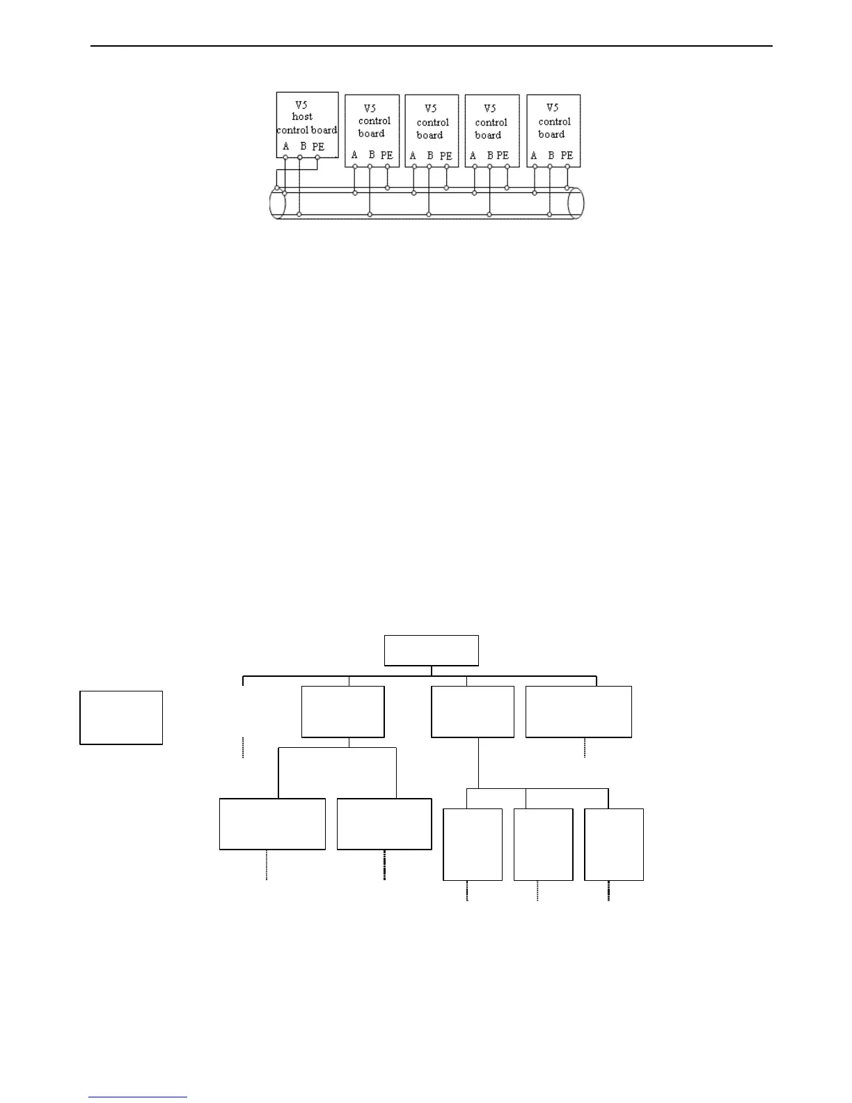
Fig.
Fig.
Fig.
Fig. 2-11
2-11
2-11
2-11 Connection
Connection
Connection
Connection of
of
of
of several
several
several
several inverters
inverters
inverters
inverters
(Inverters
(Inverters
(Inverters
(Inverters and
and
and
and motors
motors
motors
motors are
are
are
are all
all
all
all grounded
grounded
grounded
grounded well
well
well
well )
)
)
)
If the communication is still failed with the above connection methods
,
you can adopt the following measures:
(1) Use separate power supply for PLC or isolate the power supply .
(2) Use magnetism ring for the cable and reduce the inverter
’
s carrier frequency .
2-6.
2-6.
2-6.
2-6. Mounting
Mounting
Mounting
Mounting guid
guid
guid
guid
e
e
e
e
according
according
according
according with
with
with
with EMC
EMC
EMC
EMC requirement
requirement
requirement
requirement
As the inverter
’
s output wave is PWM, electro magnetic noise will be inevitably generated while it is working.To reduce the
inverter
’
s disturbance for the external devices, this chapter introduce s the mounting method in the following aspects:
control the noise, local wiring
,
grounding, leak current, usage of power supply filter.
2-6-1.
2-6-1.
2-6-1.
2-6-1. Control
Control
Control
Control the
the
the
the noise
noise
noise
noise
1. Noise type
The noise made
by
inverter
may
a ffect the neaby equipments and the effection is related to inveter
’
s control system,
antinoise and anti - jamming ability of the devices, wiring environment, saf e
ty
distance, grounding method and other
factors.The noise contains the following types: electrostatic induction, circuit transmit, space transmit, electro magnetic
induction and so on.
 Loading...