81
Fig.
Fig.
Fig.
Fig. 4-37
4-37
4-37
4-37 Limits
Limits
Limits
Limits of
of
of
of deviation
deviation
deviation
deviation Fig.
Fig.
Fig.
Fig. 4-38
4-38
4-38
4-38 close-loop
close-loop
close-loop
close-loop preset
preset
preset
preset frequency
frequency
frequency
frequency
0:
0:
0:
0: Positive
Positive
Positive
Positive
.
.
.
. When the reference increases, it will be enabled when the motor speed increase.
1:
1:
1:
1:
Negative
Negative
Negative
Negative .
.
.
. When the reference increases, it will be enabled when the motor speed reduces
Note : Define the relationship of reference and speed.
0 : Stop integral adjustment selection when the frequency reaches upper limit or lower limit s
1 : Continue the integral adjustment selection when the frequency reaches hig h limit or lower limit s
For the system need quick response, can cel the continuouse integral adjustment is recommended.
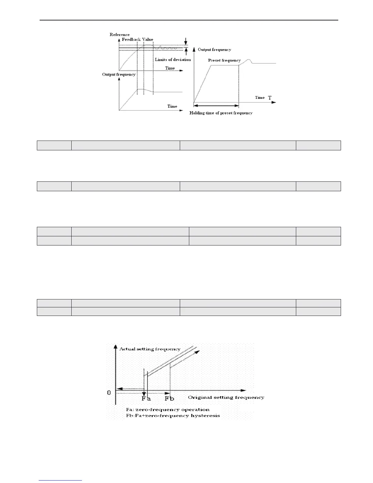
This function can make the close-loop adjustment enter stable stage quickly.
When
the
close-loop
starts,
the
f
requency will accelerate
to
the preset value set
by
P7.16
according
to Acc
time
and
the
inverter
will
running wit h
this freuquency
in
the
holding time
set
by
P7.17,
then running according
to
close-lood
character,
as
shown
in
Fig4-38.
Note
Note
Note
Note : If the function of close-loop preset frequency is not needed, you can set the preset frequency and holding time as 0.
The two function parameter is used for setting PI threshold and hysteresis of zero-frequency operation
.
If you set the frequency as
0
Hz
,
PI threshold of zero-frequency operation will be disa b led.
Fig.
Fig.
Fig.
Fig. 4-39
4-39
4-39
4-39 zero-frequency
zero-frequency
zero-frequency
zero-frequency hysteresis
hysteresis
hysteresis
hysteresis
As shown in Fig. 4-39
Start process :
 Loading...