58
Fig.
Fig.
Fig.
Fig. 4-6
4-6
4-6
4-6 Acc/Dec
Acc/Dec
Acc/Dec
Acc/Dec time
time
time
time
Note
Note
Note
Note
:
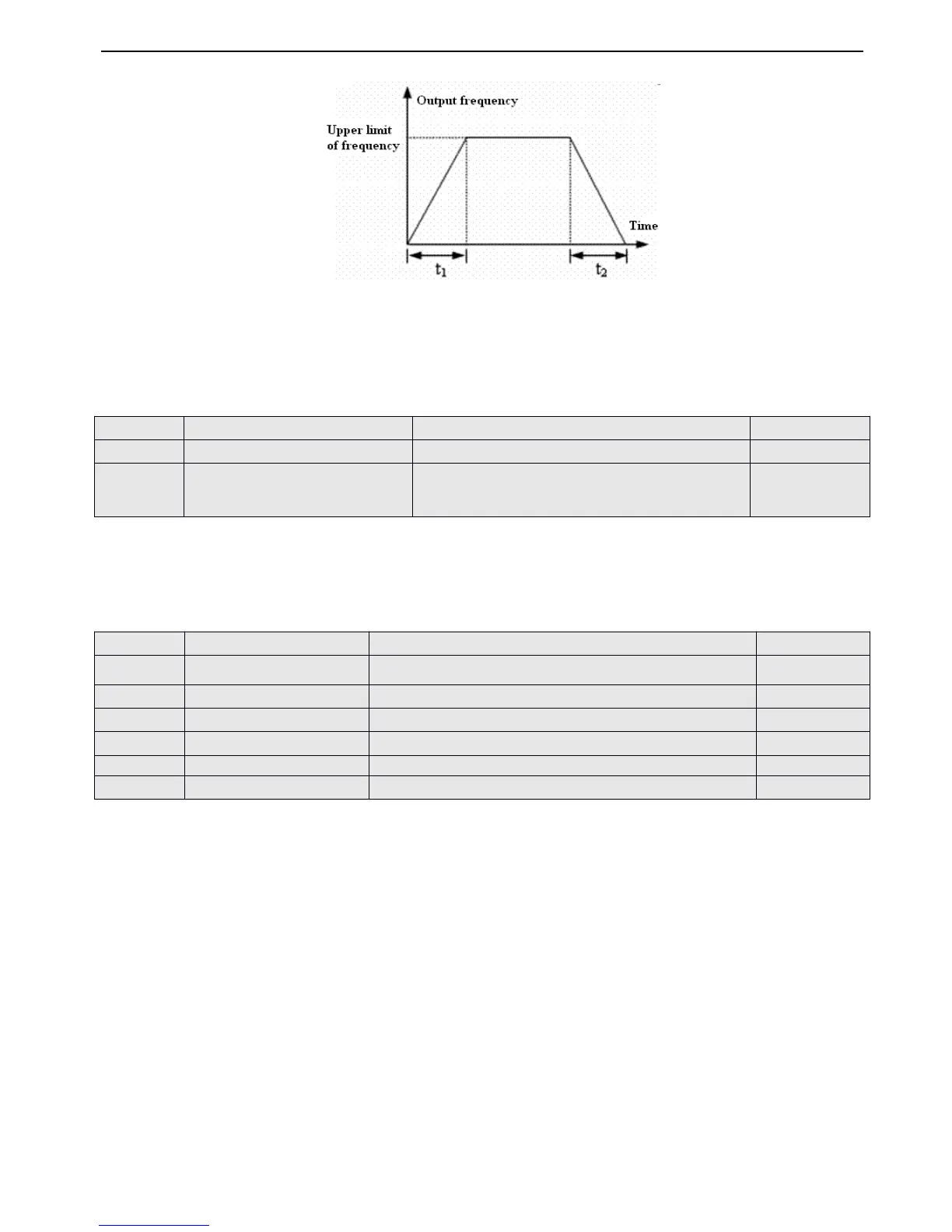
(1) This series inverter defines seven kinds of Acc/Dec time. Here only defines A cc/Dec time 1
,
Acc/Dec time 2~7 ar e
defined in P3.14~P3.25.
(2) M inute and second as the time unit of Acc/Dec time 1~7 can be selected via P0.09 and the default unit is second.
P0.19 and P0.20 define the upper and lower frequency of frequencies respectively
,
as shown in Fig.4-2 as FH and FL.
When the actual frequency is lower than the lower limit of frequency, inverter will accelerate with the accelerate time which
you have set, and then after reaching the lower limit of frequency, inverter will running with the lower limit of frequency if the
running mode is
0
and it will de celerate output frequency continuously until 0Hz with the running mode is 1.
This group of parameters define s the flex ible V/F setting modes of this inverter to satisfy the requirement of different loads.
Four fixed curve s and one user-define
d
curve can be selected according to P0.22 .
P0.22=0 , V/F curve is constant torque curv
e,
as shown in Fig.4-7 as curve
0
.
P0.22=1 , V/F cuve is 1.2 order torque-reducing curve ,
as
shown
in
Fig.
4 -
7
as
curve
1 .
P0.22=2 , V/F cuve is 1.
7
order torque-reducing curve , as shown in Fig.4-7 as curve 2.
P0.22=3 , V/F cuve is 2.0 order torque-reducing curve , as shown in Fig.4-7 as curve 3.
To
achieve best energy-saving effect, you can select 1,2 or 3 V/F curve s according to the actual loads such as fans and
pump s .
 Loading...