23
2-5-3.
2-5-3.
2-5-3.
2-5-3. Analog
Analog
Analog
Analog input/output
input/output
input/output
input/output terminal
terminal
terminal
terminal wiring
wiring
wiring
wiring
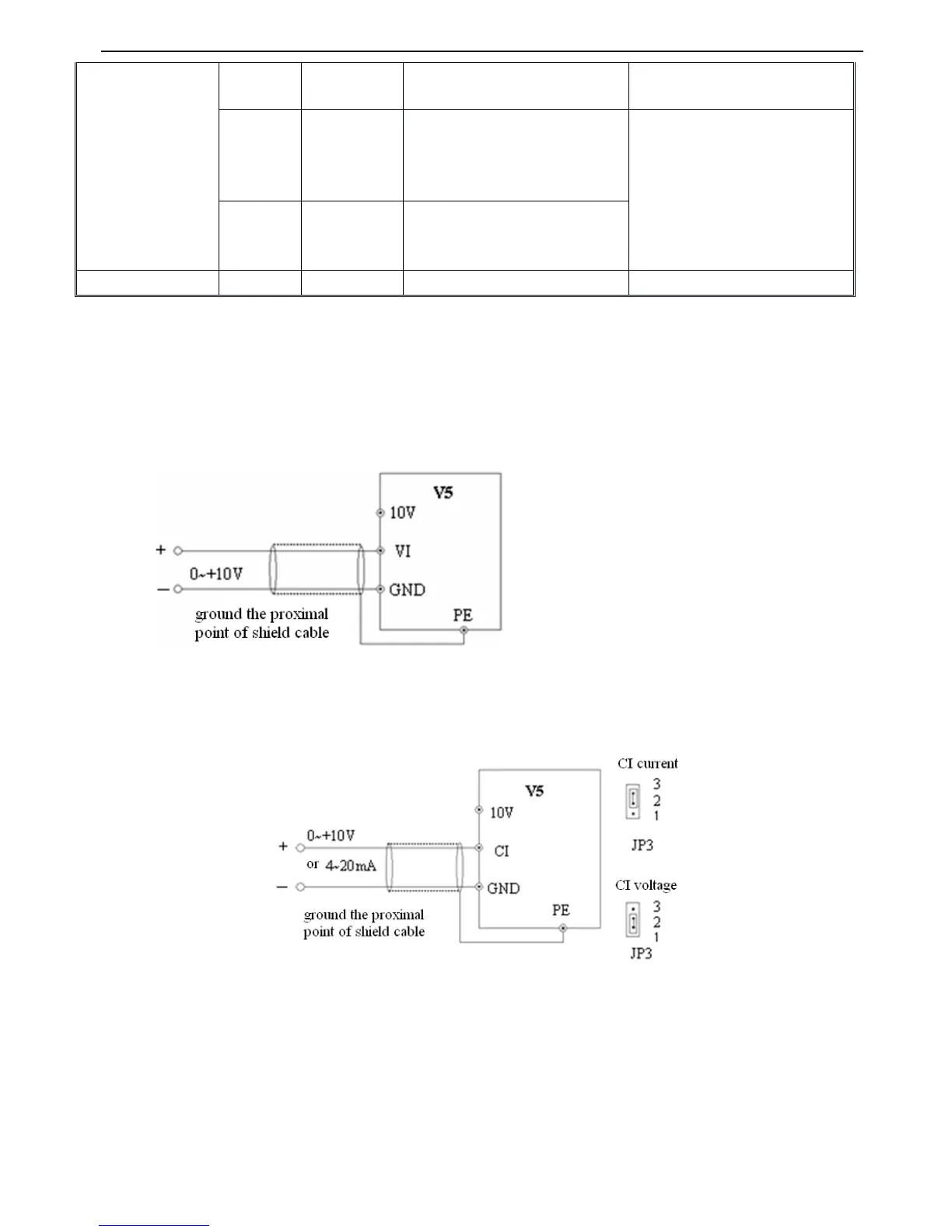
1. VI terminal voltage signal input , wiring is shown as below :
F
F
F
F ig.
ig.
ig.
ig. 2-6
2-6
2-6
2-6 VI
VI
VI
VI terminal
terminal
terminal
terminal wiring
wiring
wiring
wiring diagram
diagram
diagram
diagram
2. CI terminal analog input, jumper select voltage input (0~10V)
or
current input (4~20mA)
,
wiring is shown as below :
Fig.
Fig.
Fig.
Fig. 2-7
2-7
2-7
2-7 CI
CI
CI
CI terminals
terminals
terminals
terminals
’
’
’
’
wiring
wiring
wiring
wiring
3. Wiring for a nalog ouput terminal AO
Analog output terminal AO can display various physical quantities w hen connecting external analog meter, output voltage
0~10V,
output current 4~20mA, wiring is shown in Fig.2-8 .
 Loading...