71
and the setting of start/stop control, direction, Acc/Dec time mode in low level operation.
Note
Note
Note
Note : Switching between close-loop operation and low level operation can be realized only when close-loop is enabled
( P7.00 =1 ).
28
28
28
28 : Pause
Pause
Pause
Pause the
the
the
the PLC
PLC
PLC
PLC operation
operation
operation
operation
.
.
.
.
The terminal is used to realize pause control, when this terminal is enabled, the inverter wil l
run in
0
Hz and PLC will not accumulate time; when this terminal is disabled, inverter will start with auto speed and PLC
continue to run. Refer to group P8 for instructions.
29
29
29
29 : PLC
PLC
PLC
PLC disabled
disabled
disabled
disabled
.
This terminal can be used to flexible switching the PLC operation and low level operation.
Note
Note
Note
Note
:
The switching between PLC operation and low level operation only when PLC is running ( the unit
’
s place of P8.00 i s
not to
0
)
30
30
30
30 : Reset PLC stopping status. When PLC is in stopping status, the enabled terminal can clear PLC running stage
,
running
time, running frequency and other informations of PLC stopping memory. Refer to P8 for instructions.
31
31
31
31 : Frequency
Frequency
Frequency
Frequency reference
reference
reference
reference is
is
is
is input
input
input
input via
via
via
via CI
CI
CI
CI
.
Frequency reference is input via CI forcibly when the terminal is enabled, and it
will involute when the terminal is disabled.
32
32
32
32 : Counter
Counter
Counter
Counter
’
’
’
’
s
s
s
s trig
trig
trig
trig signal
signal
signal
signal input
input
input
input
.
.
.
.
T his terminal is used to input pulse signal to the internal counter of the inverter
.
The
highest pulse frequency is 200Hz. The present counting value can be saved at power off. See P4.2 2 and P4.2 3 for details.
33
33
33
33 : Counter
Counter
Counter
Counter
’
’
’
’
s
s
s
s zero-cleaning
zero-cleaning
zero-cleaning
zero-cleaning signal
signal
signal
signal input
input
input
input .
.
.
. I t is used to clear the counter to zero in conjunction with terminal 43.
34
34
34
34 : External
External
External
External interrupt
interrupt
interrupt
interrupt input
input
input
input .
.
.
. After receiving external interrupt input signal, inverter will lock output and running in
0
Hz
,
once the interrupt input signal release
,
the inverter will start on the fly and continue the PLC operation.
35
35
35
35
:
Pulse
Pulse
Pulse
Pulse frequency
frequency
frequency
frequency input
input
input
input ( only
only
only
only valid
valid
valid
valid for
for
for
for X6
X6
X6
X6
)
.
.
.
. This terminal can receive pulse signal as reference frequency, please re fer
to P1.11~P1.15 for the relationship between pulse frequency of input signal and reference frequency.
36:
36:
36:
36: Autual
Autual
Autual
Autual length
length
length
length clearing
clearing
clearing
clearing input
input
input
input
.
.
.
.
If this terminal is enabled, the autual length parameter P9.09 will be cleared to zero.
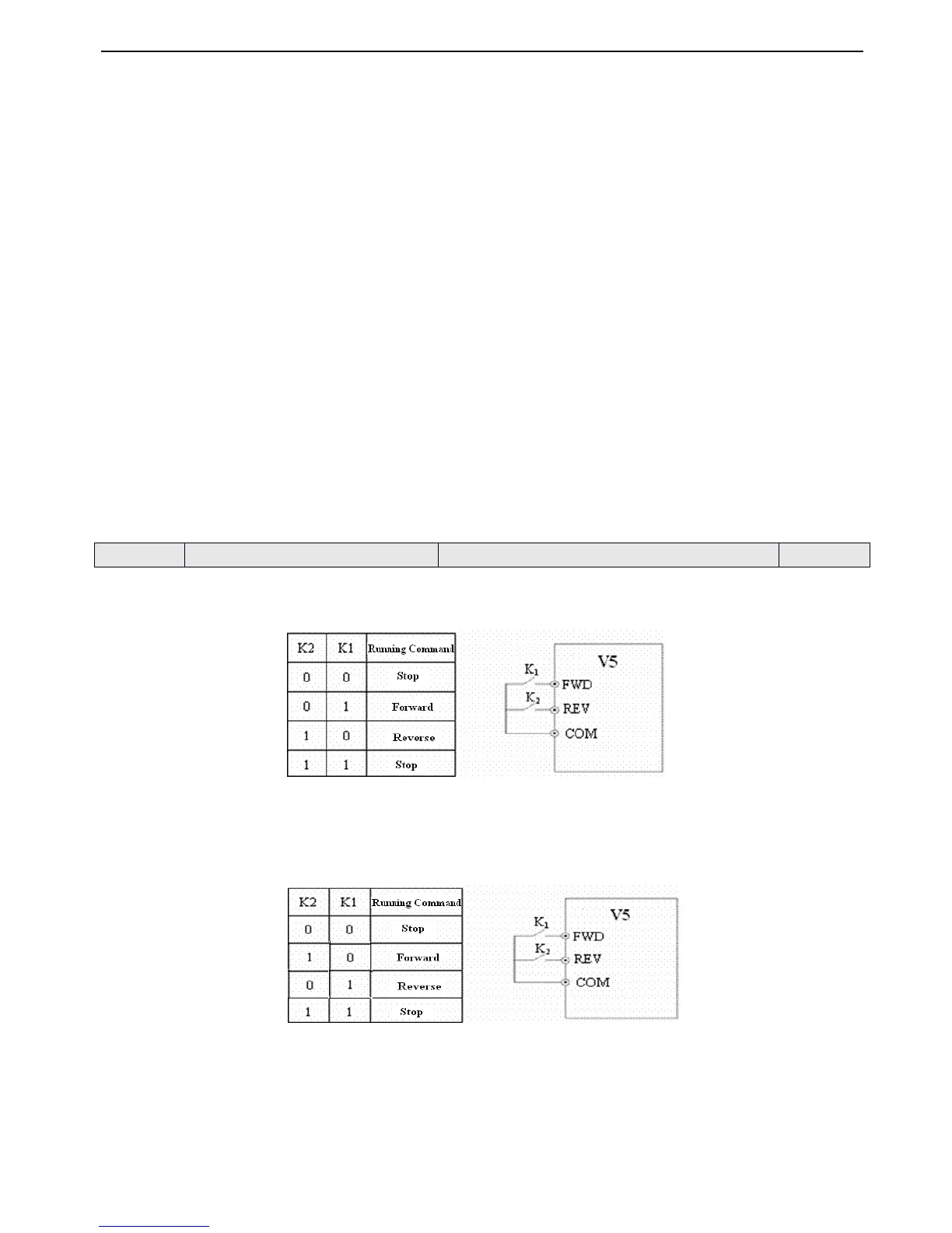
This parameter defineds four operaion modes via which external terminals can control inverter.
0
0
0
0 : 2-wire
2-wire
2-wire
2-wire control
control
control
control mode
mode
mode
mode 1
1
1
1
Fig.
Fig.
Fig.
Fig. 4-21
4-21
4-21
4-21 2-wire
2-wire
2-wire
2-wire operation
operation
operation
operation mode
mode
mode
mode 1
1
1
1
1
1
1
1 : 2-wire
2-wire
2-wire
2-wire control
control
control
control mode
mode
mode
mode 2
2
2
2
Fig.
Fig.
Fig.
Fig. 4-22
4-22
4-22
4-22 2-wire
2-wire
2-wire
2-wire operation
operation
operation
operation mode
mode
mode
mode 2
2
2
2
2
2
2
2 : 3-wire
3-wire
3-wire
3-wire control
control
control
control mode
mode
mode
mode 1
1
1
1
SB1 : Stop button
SB2 : Forward button
SB3 : Reverse button
 Loading...