30
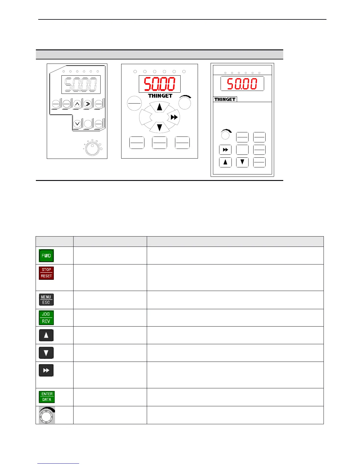
panel and control terminals, operation panel is shown in Fig.3-2.
Fig.
Fig.
Fig.
Fig. 3-2
3-2
3-2
3-2 Illustration
Illustration
Illustration
Illustration of
of
of
of operation
operation
operation
operation panel
panel
panel
panel
3-2-2.
3-2-2.
3-2-2.
3-2-2. Keyboard
Keyboard
Keyboard
Keyboard function
function
function
function
There are
8
keys and 1 analog potentiometer o n operation panel and the function
s
are shown in the following table .
VB3
VB3
VB3
VB3 0.4~0.75KW
0.4~0.75KW
0.4~0.75KW
0.4~0.75KW
VB5-OPU-01
VB5-OPU-01
VB5-OPU-01
VB5-OPU-01
V5-OPU-03
V5-OPU-03
V5-OPU-03
V5-OPU-03
MENU
ESC
JOG
REV
ENT
DATA
FWD
STOP
RESET
FWD REV ALM HZ V A
MENU
ESC
FWD
ENT
DATA
JOG
REV
STOP
RESET
FWD REV
ALM HZ V A
MENU
ESC
ENTER
DATA
FWD
JOG
REV
STOP
RESET
FWD REV ALM HZ V A
Function
Function
Function
Function
In operate panel control mode, press this key to run forward
I n operate panel control mode, press this key to stop running or return to normal
state
when inverter is in error state.
Enter or exit programming state
P3.45=0 , jog running
P3.45=1 , reverse run ning
Increase data or function code
Decrease data or function code
In editing state, press this key to select the bit to be changed; in other state, press this
key to see the monitor parameters.
In program state, press this key to enter the next menu or saving the parameters.
When P0.01=0, adjust
analog
potentiometer to change the inverter
’
s output
frequency.
 Loading...