68
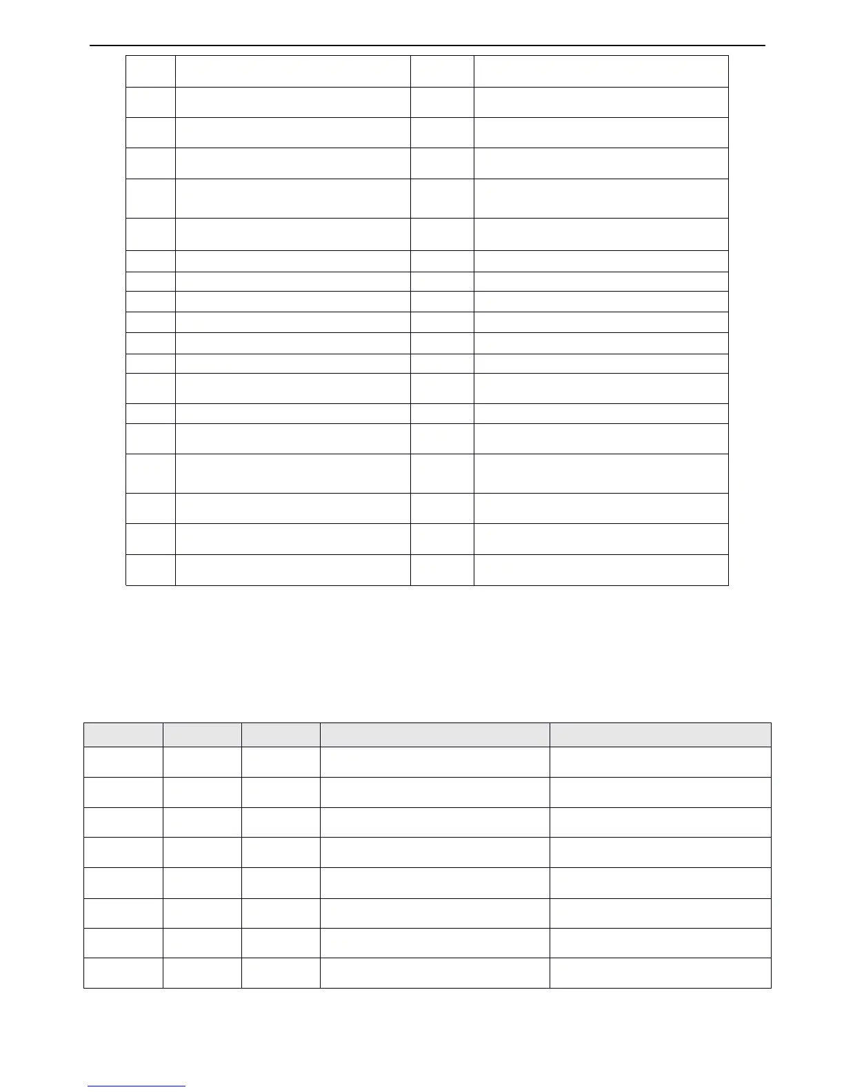
I ntroduction s of the functions shown in Table4-1:
1
1
1
1 ~ 3
3
3
3 : Multi-step
Multi-step
Multi-step
Multi-step speed
speed
speed
speed control
control
control
control terminals
terminals
terminals
terminals
.
.
.
.
Up to
7
speed reference can be set
by
different ON/OFF (open/close)
combination of the function terminals
,
at the same time
,
you can select corresponding Acc/Dec time
.
Table
Table
Table
Table
4-2
4-2
4-2
4-2 On/
On/
On/
On/ O
O
O
O ff
ff
ff
ff combination
combination
combination
combination of
of
of
of function
function
function
function terminals
terminals
terminals
terminals
The above frequenc ies can be used in multi-step speed running and simple PLC running, this manual take multi-step speed
running as an example.
Control terminal l eave unused
Multi-step speed control terminal 1
Multi-step speed control terminal 2
Multi-step speed control terminal 3
Terminal control mode is forcibly enabled
Exteral terminal for forward jog operation
Exteral terminal for reverse jog operation
Res e t traverse operatio n
Reset PLC stopping status
DC injection braking command DB
Frequency reference is input via CI
Inverter running prohibit
Counter
’
s trig signal input
Counter
’
s zero-cleaning signal input
Frequency ramp down ( DOWN )
P ulse frequency input ( only valid for X6 )
Reset signal ( clear fault )
Autual length clearing input
External fault signal normally open input
Frequency
Frequency
Frequency
Frequency setting
setting
setting
setting
Acc/Dec
Acc/Dec
Acc/Dec
Acc/Dec time
time
time
time
Acc/Dec
Acc/Dec
Acc/Dec
Acc/Dec time
time
time
time 1
Acc/Dec
Acc/Dec
Acc/Dec
Acc/Dec time
time
time
time 1
Acc/Dec
Acc/Dec
Acc/Dec
Acc/Dec time
time
time
time 2
Acc/Dec
Acc/Dec
Acc/Dec
Acc/Dec time
time
time
time 3
Acc/Dec
Acc/Dec
Acc/Dec
Acc/Dec time
time
time
time 4
Acc/Dec
Acc/Dec
Acc/Dec
Acc/Dec time
time
time
time 5
Acc/Dec
Acc/Dec
Acc/Dec
Acc/Dec time
time
time
time 6
6
6
6
Acc/Dec
Acc/Dec
Acc/Dec
Acc/Dec time
time
time
time 7
 Loading...