4.6 Items to Check before Starting Up the Drive
136 YASKAWA SIEPC71061753C GA500 Technical Manual
4.6 Items to Check before Starting Up the Drive
◆ Check before You Energize the Drive
Check the items in Table 4.5 before you energize the drive.
Table 4.5 Items to Check before You Energize the Drive
Items to Check Description
Input Power Supply Voltage
The voltage of the input power supply must be:
Single-phase 200 V class: single-phase 200 Vac to 240 Vac 50/60 Hz, 270 Vdc to 340 Vdc
Three-phase 200 V class: three-phase 200 Vac to 240 Vac 50/60 Hz, 270 Vdc to 340 Vdc
Three-phase 400 V class: three-phase 380 Vac to 480 Vac 50/60 Hz, 513 Vdc to 679 Vdc
Correctly wire power supply input terminals R/L1, S/L2, and T/L3, or L and N.
Correctly ground the drive and motor.
Connection between Drive Output
Terminals and Motor Terminals
Make sure that you connected drive output terminals U/T1, V/T2, and W/T3 in the correct sequence to align with motor terminals U,
V, and W and tighten the screws to a correct tightening torque.
Control Circuit Terminal Wiring
Make sure that you connected the drive control circuit terminals in the correct sequence to align with devices and switches and tighten
the screws to a correct tightening torque.
Control Circuit Terminal Status
Turn OFF the inputs from all devices and switches connected to the drive control circuit terminals.
Connection between Machinery and
Motor
Disengage all couplings and belts that connect the motor and machinery.
◆ Check after You Energize the Drive
Check the items in Table 4.6 after you energize the drive. The keypad display is different depending on drive
status.
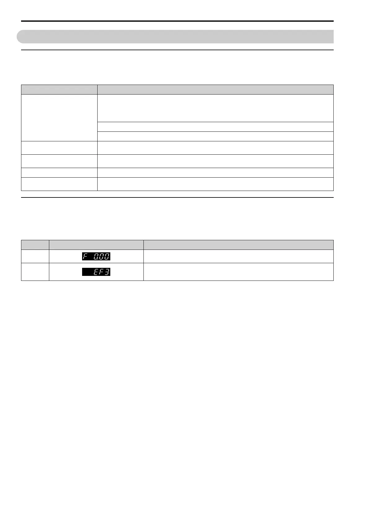
Table 4.6 Display Status after You Energize the Drive
Status Display Description
During Usual
Operation
The LED display shows the frequency reference.
When the
Drive Detects
a Fault
The display is different for different faults. Refer to “Troubleshooting” to remove the cause of the fault.
The ALM/ERR LED will illuminate.
 Loading...


