3.5 Control Circuit Wiring
94 YASKAWA SIEPC71061753C GA500 Technical Manual
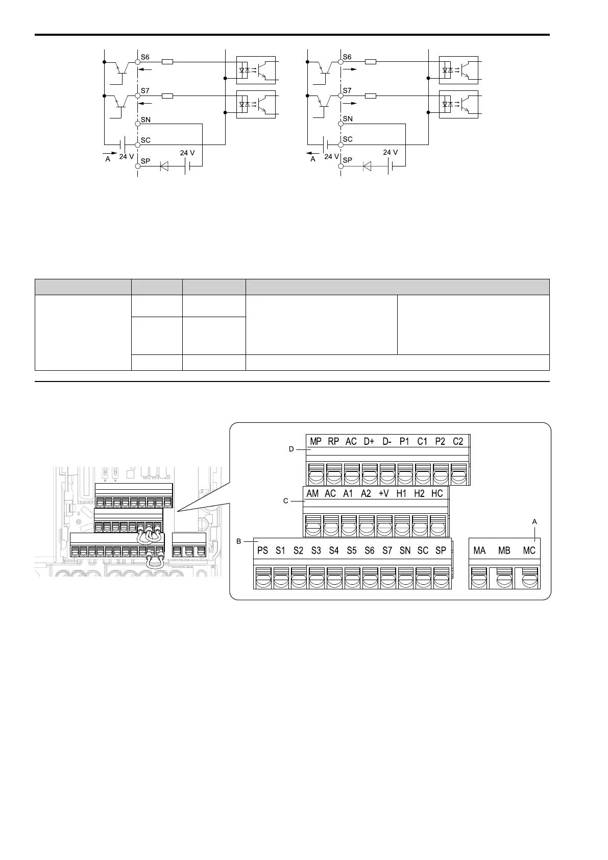
A - External power supply
Figure 3.38 Wiring MFDI Terminals
■ Serial Communication Terminals
Refer to Table 3.10 for a list of serial communication terminals and functions.
Table 3.10 Serial Communication Terminals
Type Terminal Terminal Name Function (Signal Level)
Modbus Communication
D+
Communication
input/output (+)
MEMOBUS/Modbus communications
Use an RS-485 cable to connect the drive.
Note:
Set DIP switch S2 to ON to enable the
termination resistor in the last drive in a
MEMOBUS/Modbus network.
• RS-485
• MEMOBUS/Modbus communication protocol
• Maximum 115.2 kbps
D-
Communication
output (-)
AC Shield ground
0 V
◆ Control Circuit Terminal Configuration
The control circuit terminals are in the positions shown in Figure 3.39.
A - Terminal block (TB2)
B - Terminal block (TB1-1)
C - Terminal block (TB1-2)
D - Terminal block (TB1-3)
Figure 3.39 Control Circuit Terminal Arrangement
■ Control Circuit Wire Gauges and Tightening Torques
Use the tables in this section to select the correct wires. Use shielded wire to wire the control circuit terminal
block. Use crimp ferrules on the wire ends to make the wiring procedure easier and more reliable.
 Loading...


