Electrical Installation
3
3.3 Main Circuit Wiring
YASKAWA SIEPC71061753C GA500 Technical Manual 81
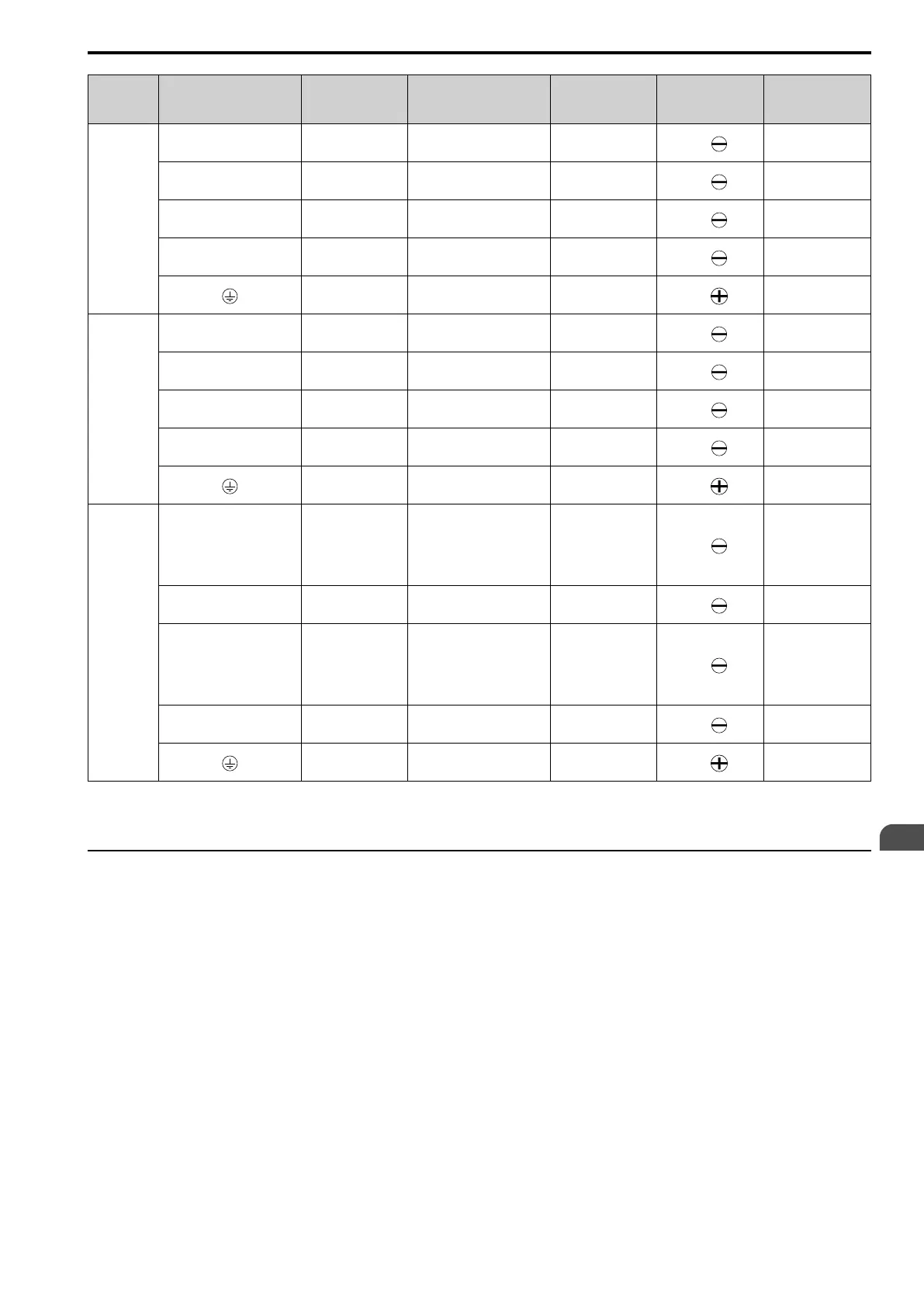
Model Terminal
Recomm. Gauge
mm
2
Applicable Gauge
mm
2
Wire Stripping
Length
*1
mm
Terminal Screw
Size and Shape
Tightening Torque
N∙m (lbf∙in)
4038
R/L1, S/L2, T/L3 10 4 - 16 10
M4
1.5 - 1.7
(13.5 - 15)
U/T1, V/T2, W/T3 6 2.5 - 10 10
M4
1.5 - 1.7
(13.5 - 15)
-, +1, +2 16 4 - 25 18
M5
2.3 - 2.5
(19.8 - 22)
B1, B2 4 2.5 - 6 10
M4
1.5 - 1.7
(13.5 - 15)
10 6 - 16 -
M6
5.4 - 6.0
(47.8 - 53.1)
4044
R/L1, S/L2, T/L3 16 4 - 25 18
M5
2.3 - 2.5
(19.8 - 22)
U/T1, V/T2, W/T3 10 4 - 16 18
M5
2.3 - 2.5
(19.8 - 22)
-, +1, +2 16 6 - 25 18
M5
2.3 - 2.5
(19.8 - 22)
B1, B2 6 4 - 10 10
M4
1.5 - 1.7
(13.5 - 15)
10 6 - 16 -
M6
5.4 - 6.0
(47.8 - 53.1)
4060
R/L1, S/L2, T/L3 25 6 - 35 18
M5
• ≤ 25 mm
2
2.3 - 2.5
(19.8 - 22)
• 35 mm
2
≤
4.1 - 4.5
(36 - 40)
U/T1, V/T2, W/T3 16 4 - 25 18
M5
2.3 - 2.5
(19.8 - 22)
-, +1, +2 25 6 - 35 18
M5
• ≤ 25 mm
2
2.3 - 2.5
(19.8 - 22)
• 35 mm
2
≤
4.1 - 4.5
(36 - 40)
B1, B2 10 2.5 - 16 10
M4
1.5 - 1.7
(13.5 - 15)
10 6 - 16 -
M6
5.4 - 6.0
(47.8 - 53.1)
*1 Remove insulation from the ends of wires to expose the length of wire shown.
*2 If you turn on the internal EMC filter, the leakage current of the drive will be more than 3.5 mA. Use the closed-loop crimp terminals
to connect a protective ground wire that has a minimum cross-sectional area of 10 mm
2
(copper wire).
◆ Main Circuit Terminal and Motor Wiring
This section outlines the various steps, precautions, and checkpoints for wiring the main circuit terminals and
motor terminals.
WARNING! Fire Hazard. Do not connect main power supply wiring to drive motor terminals U/T1, V/T2, and W/T3. Connect
main power supply wiring to main circuit input terminals R/L1, S/L2, and T/L3. Incorrect wiring can cause serious injury or death
from fire.
WARNING! Sudden Movement Hazard. Make sure that you align the phase order for the drive and motor when you connect the
motor to drive output terminals U/T1, V/T2, and W/T3. If the phase order is incorrect, it can cause the motor to run in reverse. If
the motor accidentally runs in reverse, it can cause serious injury or death.
NOTICE: Do not connect phase-advancing capacitors, LC/RC noise filters, or leakage breakers (RCM/RCD) to the motor
circuit. If you connect these devices to the output circuits, it can cause damage to the drive and connected equipment.
■ Cable Length Between Drive and Motor
When the wiring between the drive and the motor is too long, voltage drop along the motor cable can decrease
motor torque, usually at low frequency output. If you connect motors in parallel with long motor cable, this is also
a problem. Drive output current increases when the leakage current from the cable increases. An increase in
leakage current can cause overcurrent and decrease the precision of the current detection.
 Loading...


