Mechanical Installation
2
2.10 Conditions
YASKAWA SIEPC71061753C GA500 Technical Manual 49
Table 2.22 Maximum Temperature of the Heatsink Plate
Model Maximum Temperature of the Heatsink Plate
B001 - B012 90 °C (194 °F)
2001 - 2021 90 °C (194 °F)
2030 - 2070 80 °C (176 °F)
4001 - 4012 90 °C (194 °F)
4018 - 4038 80 °C (176 °F)
Refer to Single-Phase 200 V Class on page 36, Three-Phase 200 V Class on page 37, and Three-Phase 400 V
Class on page 38 for the drive watt loss data.
Refer to Monitor Heatsink Plate Temperature on page 49 to monitor drive heatsink plate temperature.
■ Monitor Heatsink Plate Temperature
• When you use the drive keypad
Set U4-08 [Heatsink Temperature] to show the drive heatsink temperature.
Figure 2.13 U4-08 [Heatsink Temperature] (When the heatsink plate is 89 °C)
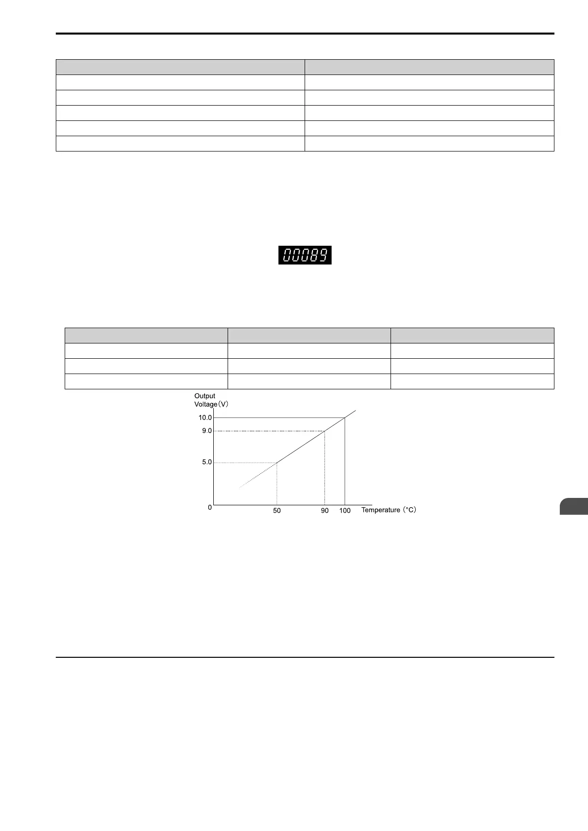
• When you use a Multi-function Analog Monitor Output
When you use terminal AM, set the parameters as shown in Table 2.23.
Table 2.23 MFAO Settings
Parameter Name Setting
H4-01 Terminal AM Analog Output Select 408 (U4-08)
H4-02 Terminal AM Analog Output Gain 100.0%
H4-03 Terminal AM Analog Output Bias 0.0%
Figure 2.14 Heatsink Plate Temperature Output on MFAO
Note:
• The accuracy is ±5 °C (41 °F) for heatsink plate temperatures between 50 °C to 100 °C (122 °F to 212 °F).
• The installation environment has an effect on the temperature.
■ Overheat Alarm Level
If the heatsink temperature is more than the temperature set in L8-02 [Overheat Alarm Level], the drive detects
oH [Heatsink Overheat]. To enable this function, set H2-0x [MFDO Function Select] to 20 [Drive Overheat Pre-
Alarm (oH)].
Use L8-03 [Overheat Alarm Level] to set the operation when the drive detects oH [Heatsink Overheat].
◆ Surface Finish of Metal Surface
Make sure that the metal surface to which you will install the drive meets these specifications:
• Flatness: ≤ 0.2 mm (0.0078 in)
• Roughness: ≤ 25 S
Note:
A roughness of 25 S means that the average roughness “Ra” is 6.3 a and the maximum peak “Rz” is 25 μm.
 Loading...


