12.8 H: Terminal Function Selection
678 YASKAWA SIEPC71061753C GA500 Technical Manual
■ 1F: Not Used
Setting Value Function Description
1F Not Used
Use this setting for unused terminals or to use terminals in through mode.
When you set a terminal that you do not use to 1F, you can use the signal that is input to that terminal as the PLC
analog signal input from MEMOBUS/Modbus communications or the communication option. This input signal
does not have an effect on drive operation. This signal functions the same as F (Through Mode).
■ 30: DWEZ Analog Input 1
Setting Value Function Description
30 DWEZ Analog Input 1
Use with DriveWorksEZ. Refer to the DriveWorksEZ online manual for more information.
■ 31: DWEZ Analog Input 2
Setting Value Function Description
31 DWEZ Analog Input 2
Use with DriveWorksEZ. Refer to the DriveWorksEZ online manual for more information.
◆ H4: Analog Outputs
H4 parameters set the drive analog monitors. These parameters select monitor parameters, adjust gain and bias,
and select output signal levels.
■ Calibrate Meters Connected to MFAO Terminal AM
Use these parameters to calibrate meters connected to terminal AM:
• H4-02 [Terminal AM Analog Output Gain]
• H4-03 [Terminal AM Analog Output Bias]
Set these parameters where the output voltage of 10 V and output current of 20 mA are 100% of the signal level.
Use jumper switch S5 and parameter H4-07 [Terminal AM Signal Level Select] to set the voltage output and
current output.
No. Name Range Default
H4-02 Terminal AM Analog Output Gain -999.9 - +999.9% 100.0%
H4-03 Terminal AM Analog Output Bias -999.9 - +999.9% 0.0%
H4-07 Terminal AM Signal Level Select
0: 0 +10 VDC
2: 4-20 mA
0
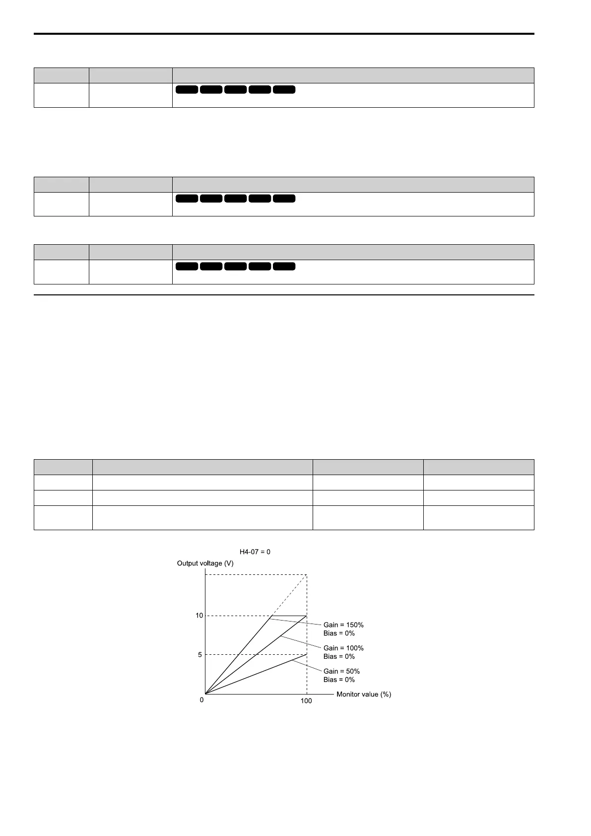
Figure 12.98 and Figure 12.99 show the gain and bias.
Figure 12.98 Analog Output Gain/Bias Configuration Example 1
For example, when the parameter value set to analog output is 0, and a 3 V signal is to be output to terminal AM,
set H4-03 [AM Analog Output Bias] = 30%.
 Loading...


