8 Operation
8.3.3 Setting the Overtravel Limit Function
8-20
8.3.3 Setting the Overtravel Limit Function
The overtravel limit function forces movable machine parts to stop if they exceed the allowable range of motion
and turn ON a limit switch.
(1) Connecting the Overtravel Signal
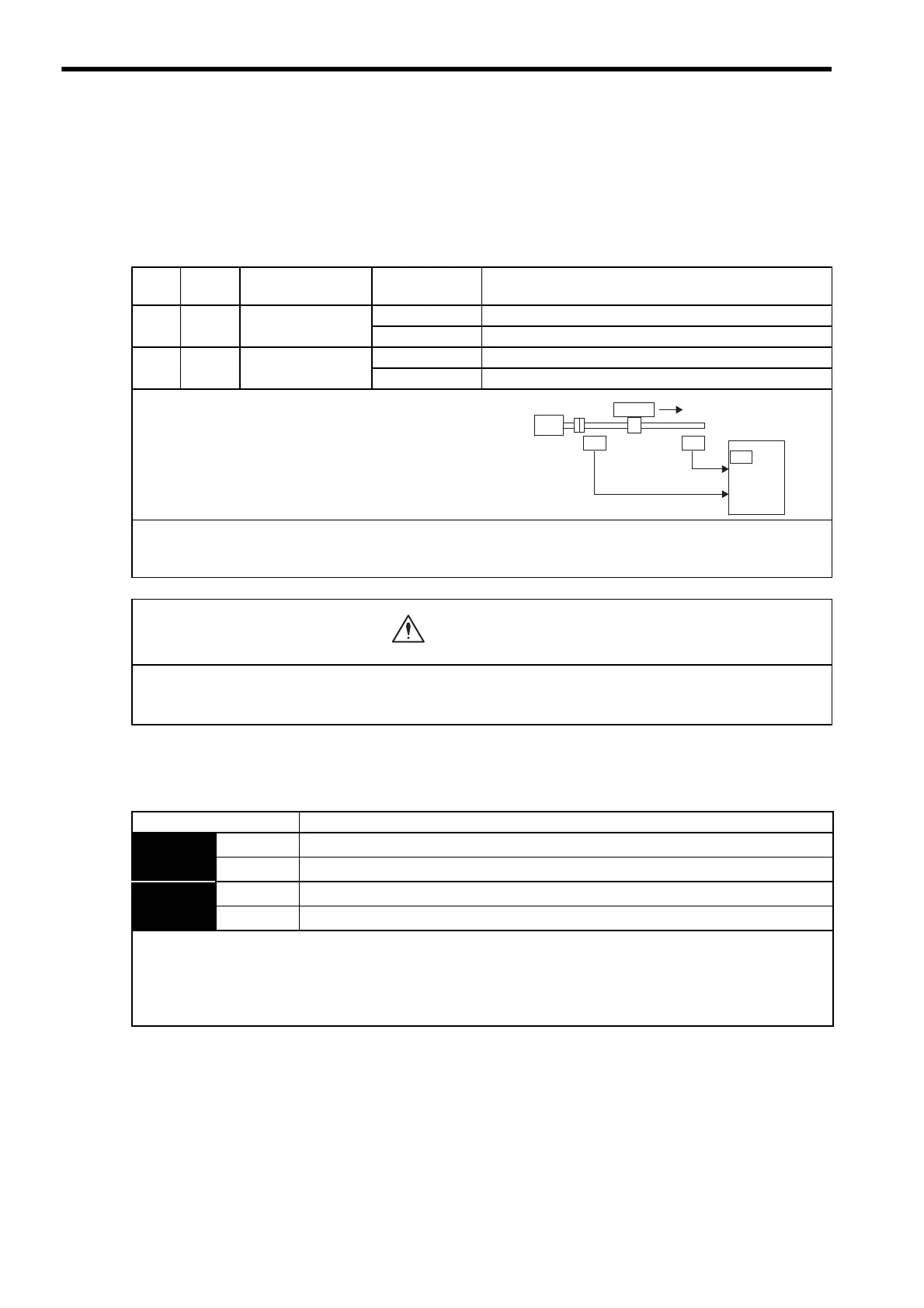
To use the overtravel function, connect the following overtravel limit switch input signal terminals.
(2) Enabling/Disabling the Overtravel Signal
A parameter can be set to disable the overtravel signal. If the parameter is set, there is no need to wire the over-
travel input signal.
Type Name
Connector Pin
Number
Setting Meaning
Input P-OT
CN1-42
(Factory setting)
ON (low level) Forward rotation allowed. Normal operation status.
OFF (high level) Forward rotation prohibited. Forward overtravel.
Input N-OT
CN1-43
(Factory setting)
ON (low level) Reverse rotation allowed. Normal operation status.
OFF (high level) Reverse rotation prohibited. Reverse overtravel.
Connect limit switches as shown below to prevent damage to
the devices during linear motion.
Rotation in the opposite direction is possible during overtravel.
For example, reverse rotation is possible during forward over-
travel.
IMPORTANT
When the servomotor stops due to overtravel during position control, the position error pulses are held. A clear signal
(CLR) input is required to clear the error pulses.
Limit
switch
Servomotor
SERVOPACK
42
CN1
43
N-OT
P-OT
Limit
switch
Motor forward rotation direction
When using the servomotor on a vertical axis, the workpiece may fall in the overtravel condition.
To prevent this, always set the zero clamp after stopping with Pn001 = n.1.
Refer to (3) Selecting the Motor Stop Method When Overtravel is Used in this section.
Parameter Meaning
Pn50A
n.2
Inputs the Forward Run Prohibited (P-OT) signal from CN1-42. (Factory setting)
n.8
Disables the Forward Run Prohibited (P-OT) signal. (Allows constant forward rotation.)
Pn50B
n.
3
Inputs the Reverse Run Prohibited (N-OT) signal from CN1-43. (Factory setting)
n.
8
Disables the Reverse Run Prohibited (N-OT) signal. (Allows constant reverse rotation.)
• Applicable control methods: Speed control, position control, and torque control
• After changing these parameters, turn OFF the main circuit and control power supplies and then turn them ON again to
enable the new settings.
* A parameter can be used to re-allocate input connector number for the P-OT and N-OT signals. Refer to 7.3.2 Input Cir-
cuit Signal Allocation.
Artisan Technology Group - Quality Instrumentation ... Guaranteed | (888) 88-SOURCE | www.artisantg.com

 Loading...


