8.5 Operating Using Speed Control with Analog Reference
8-39
8.5.2 Setting Input Signals
(1) Speed Reference Input
Input the speed reference to the SERVOPACK using the analog voltage reference to control the servomotor speed
in proportion to the input voltage.
(2) Proportional Control Reference (/P-CON)
Type
Signal
Name
Connector Pin
Number
Name
Input
V-REF CN1-5 Speed Reference Input
SG CN1-6 Signal Ground for Speed Reference Input
The above inputs are used for speed control (analog voltage reference). (Pn000.1 = 0, 4, 7, 9, or A)
Pn300 is used to set the speed reference input gain. Refer to 8.5.1 Setting Parameters.
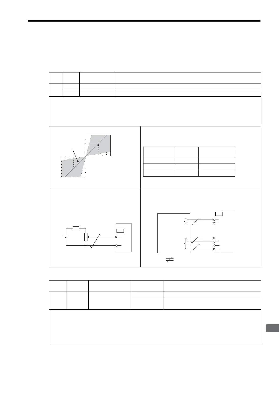
Input Specifications
• Input range: ±2 VDC to ±10 VDC/rated speed
• Maximum allowable input voltage: ±12 VDC
• Setting Example
Pn300 = 600: Rated speed at ±6 V
Actual examples are shown below.
Parameter Pn300 can be used to change the voltage input range.
Input Circuit Example
• Always use twisted-pair wire to control noise.
• Recommended variable resistor: Model 25HP-
10B manufactured by Sakae Tsushin Kogyo Co.,
Ltd.
Connect V-REF and SG to the speed reference output terminals on
the host controller when using a host controller, such as a program-
mable controller, for position control.
Type
Signal
Name
Connector
Pin Number
Setting Description
Input /P-CON CN1-41
ON (low level) Operates the SERVOPACK with proportional control.
OFF (high level)
Operates the SERVOPACK with proportional integral
control.
/P-CON signal selects either the PI (proportional integral) or P (proportional) Speed Control Mode.
Switching to P control reduces servomotor rotation and minute vibrations due to speed reference input drift.
Input reference: At 0 V, the servomotor rotation due to drift will be reduced, but servomotor rigidity (holding force) drops
when the servomotor is stopped.
Note: A parameter can be used to reallocate the input connector number for the /P-CON signal. Refer to 7.3.2 Input Circuit
Signal Allocation.
Input voltage (V)
Factory setting
Rated motor speed
Rated motor speed
The slope is set in Pn300.
-4-8-12
4812
Speed Reference
Input
Rotation
Direction
Motor Speed
+6 V Forward Rated motor speed
Forward 1/6 rated motor speed
1/2 rated motor speed
Reverse
+1 V
-3 V
CN1
5
6
SG
V-REF
2 kΩ
+12 V
SERVOPACK
1.8 kΩ 1/2 W min.
SG
V-REF
CN1
6
33
34
35
36
5
/PBO
PBO
/PAO
PAO
Feedback
pulse input
terminals
Speed reference
Host controller
output terminals
SERVOPACK
: represents twisted-pair wires.
Artisan Technology Group - Quality Instrumentation ... Guaranteed | (888) 88-SOURCE | www.artisantg.com

 Loading...


