Machine Protection
6-33
Motor Overload Protection
The motor can be protected from overload using the Inverter's built-in electronic thermal overload relay func-
tion.
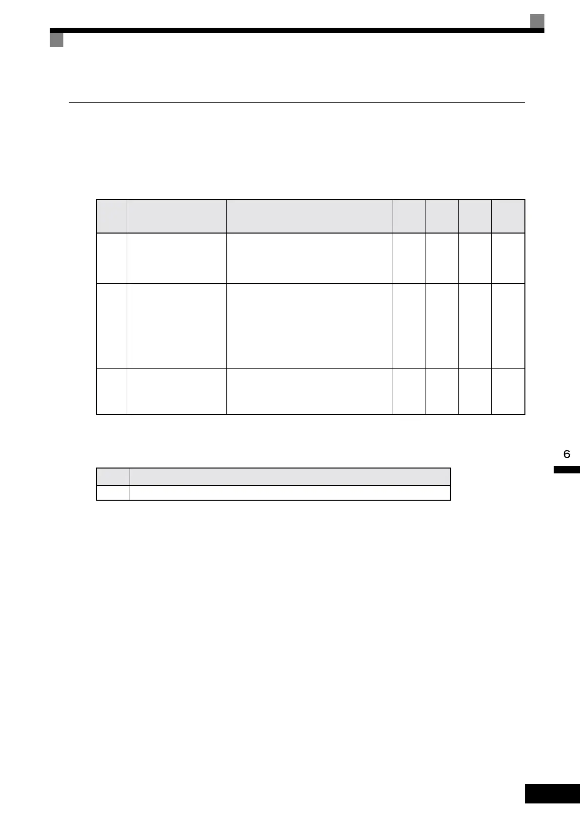
Related Constants
* 1. The settings range is 10% to 200% of the Inverter rated output current. (The values shown are for a 200 V Class Inverter with 0.4 kW.)
* 2. Factory settings depend on Inverter capacity. (The values shown are for a 200 V Class Inverter with 0.4 kW.)
Multi-Function Outputs (H2-01 to H2-03)
Setting Motor Rated Current (E2-01)
Set the rated current value on the motor nameplate in constants E2-01 (for motor 1). This set value is the base
current for the internal thermal overload calculation.
Setting Motor Overload Protection Characteristics (L1-01)
Set the overload protection function in L1-01 according to the application.
Set L1-01 to:
0: to disable the thermal motor protection function.
1: to enable the thermal motor protection for a fan cooled general purpose motor (self-cooled).
Setting Motor Protection Operation Time (L1-02)
Set the motor protection operation time in L1-02.
The motor protection operation time is the time for that the motor can handle a 150% overload when it was
running with the rated load before (i.e. operating temperature was reached before applying the 150% over-
load). Set the motor protection operation time in L1-02. The factory setting is 60 sec.
Con-
stant
Number
Name Description
Setting
Range
Factory
Setting
Change
during
Opera-
tion
Access
Level
E2-01 Motor rated current
Sets the motor rated current of motor 1.
This set value becomes the base value for motor protection
and torque limit. It is an input data for autotuning.
0.32 to
6.40
*1
1.90 A
*2
No Q
L1-01 Motor protection selection
Set to enable or disable the motor overload protection
function using the electronic thermal relay.
0: Disabled
1: General motor protection (fan cooled motor)
With applications where the power supply is often turned
ON and OFF, there is a risk that the motor cannot be pro-
tected even if this constant has been set to 1, because the
thermal value will be reset. If multiple motors are con-
nected to one Inverter, set this constant to 0, and install a
thermal relay in each motor.
0 or 1 1 No Q
L1-02 Motor protection time constant
Set the electronic thermal detection time in minutes.
Normally, there is no need to make this setting.
The factory setting is 150% overload for 1 min.
If the motor overload capability is known, set the overload
resistance protection time during hot start to L1-02.
0.1 to
5.0
1.0 min No A
Set
Value
Function
1F Motor overload (OL1, including OH3) pre-alarm (ON: 90% or more of the detection level)
Artisan Technology Group - Quality Instrumentation ... Guaranteed | (888) 88-SOURCE | www.artisantg.com
 Loading...