Wiring Control Circuit Terminals
2-19
Wiring Control Circuit Terminals
Wire Sizes
For remote operation using analog signals, keep the control line length between the Analog Operator or oper-
ation signals and the Inverter to 50 m or less, and separate the lines from main power lines or other control cir-
cuits to reduce induction from peripheral devices.
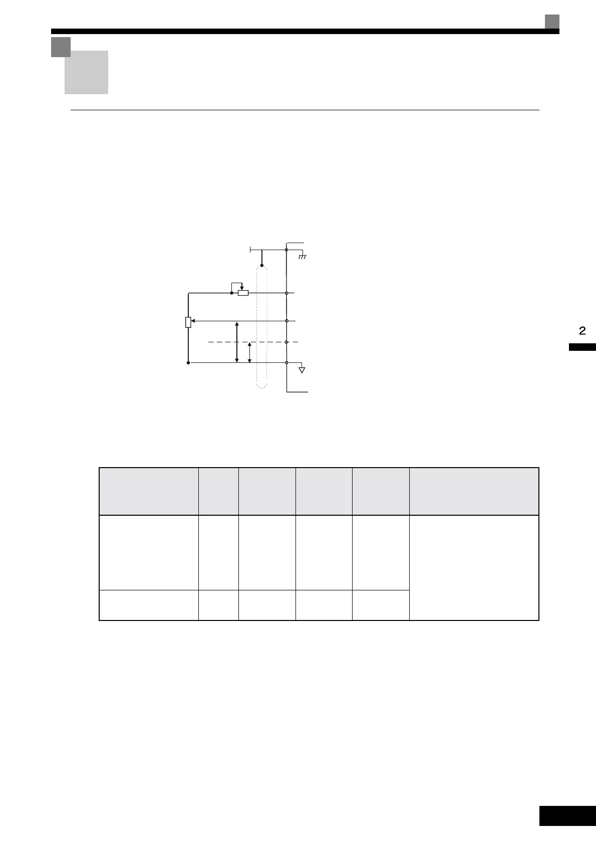
When setting frequencies from an external frequency source (and not from a Digital Operator), used shielded
twisted-pair wires and ground the shield for the largest area of contact between shield and ground. See the fig-
ure below for details on the wiring.
Fig 2.9
Terminal numbers and wire sizes are shown in Table 2.9.
* 1. Use shielded twisted-pair cables to input an external frequency reference.
* 2. Refer to Table 2.3 Lug Sizes for suitable lug sizes for the wires.
* 3. We recommend using straight solderless terminal on signal lines to simplify wiring and improve reliability.
Table 2.9 Terminal Numbers and Wire Sizes (Same for all Models)
Te r m i n a l s
Te r m i -
nal
Screws
Tightening
Torque
(N•m)
Possible
Wire Sizes
mm
2
(AWG)
Recom-
mended
Wire Size
mm
2
(AWG)
Wire Type
FM, AC, AM, SC, SP,
SN, A1, A2, +V, S1, S2,
S3, S4, S5, S6, S7
MA, MB, MC, M1, M2,
M3, M4,
R+, R-, S+, S-, IG
Phoenix
type
0.5 to 0.6
Single wire
*3
:
0.14 to 2.5
Stranded
wire:
0.14 to 1.5
(26 to 14)
0.75
(18)
• Shielded, twisted-pair wire
*1
• Shielded, polyethylene-cov-
ered, vinyl sheath cable
(KPEV-S by Hitachi Electrical
Wire or equivalent)
E (G) M3.5 0.8 to 1.0
0.5 to 2
*2
(20 to 14)
1.25
(12)
+V
AC
A2
Multi-functions analog input 2 [Default: Frequency bias,
4 to 20mA (250 )
Ω
Analog input 1: Master frequency reference
0 to +10V (20 k )
Ω
A1
0V
Analog input power supply
+15V, 20mA
E(G)
PP
4 to 20mA
0 to 10V
Analog input setting
adjustment
3
2 k
Ω
2
1
2 k
Ω
Shield
terminal
Artisan Technology Group - Quality Instrumentation ... Guaranteed | (888) 88-SOURCE | www.artisantg.com
 Loading...